Coating mixing and road line marking device
A scribing device and paint technology, applied in the direction of roads, roads, road repair, etc., can solve problems such as poor mixing uniformity of paints, and achieve the effects of improving mixing uniformity, bonding efficiency and bonding amount, and improving mixing uniformity.
- Summary
- Abstract
- Description
- Claims
- Application Information
AI Technical Summary
Problems solved by technology
Method used
Image
Examples
Embodiment 1
[0035] Embodiments of the present invention are described in detail below, examples of which are shown in the drawings, wherein the same or similar reference numerals designate the same or similar elements or elements having the same or similar functions throughout. The embodiments described below by referring to the figures are exemplary and are intended to explain the present invention and should not be construed as limiting the present invention.
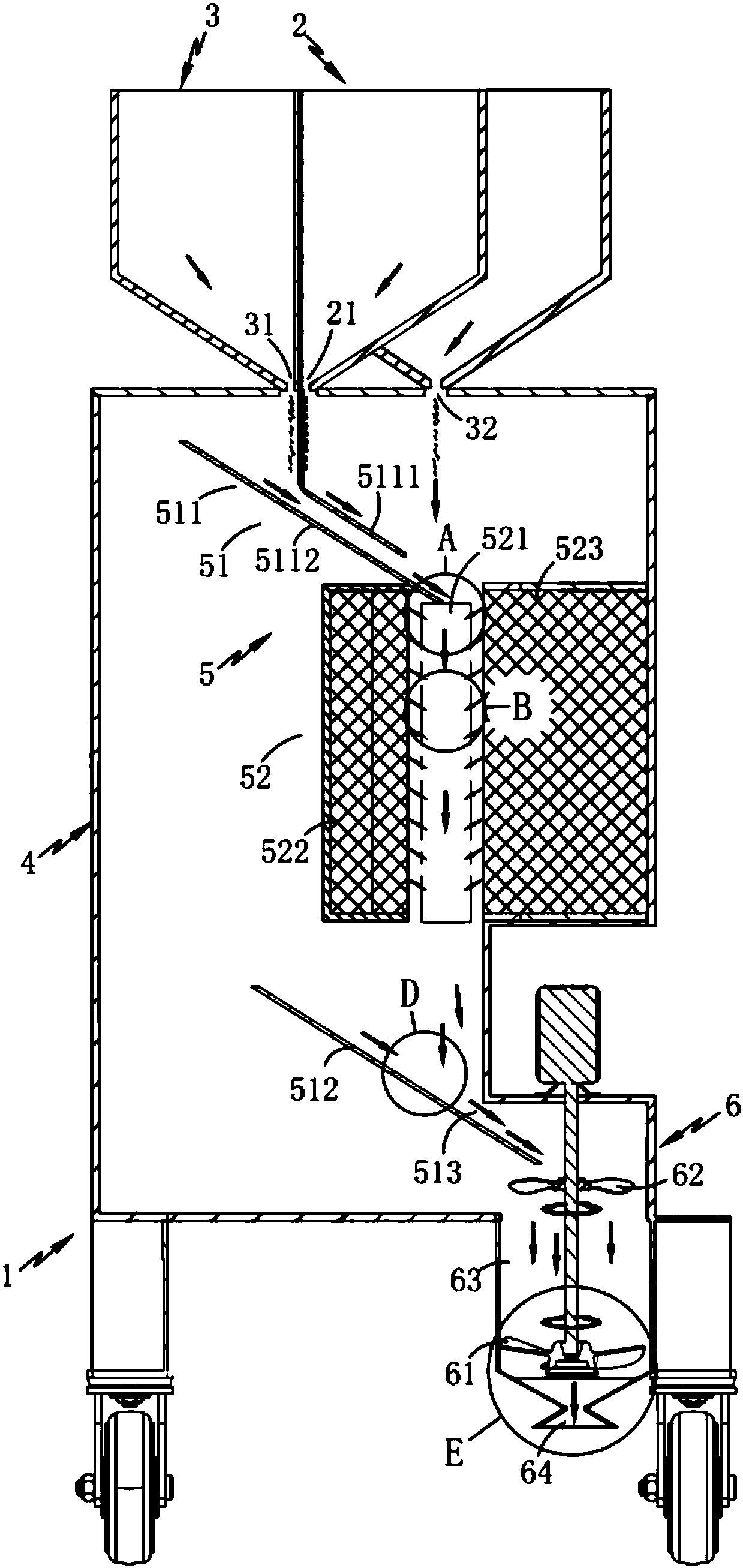
[0036] Such as figure 1 and 2 As shown, a paint mixing road marking device includes a traveling mechanism 1, a resin bin 2, a powder bin 3 and a melting bin 4, and also includes:
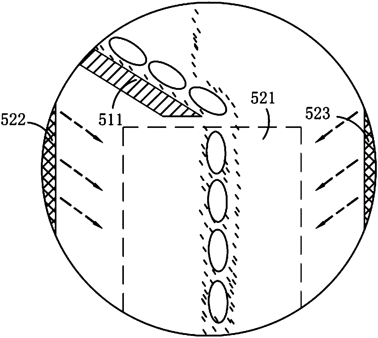
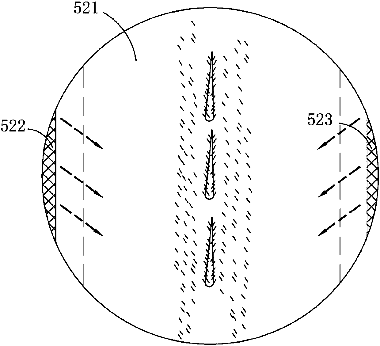
[0037] Mixing and melting mechanism 5, the mixing and melting mechanism 5 is located inside the melting chamber 4, which includes a transfer assembly 51 for resin and powder transfer and a hot melt assembly 52, through the first transfer assembly 511 in the transfer assembly 51, respectively After conducting the conduction of the resin and the powder...
Embodiment 2
[0042] Such as Figure 4 and 5 As shown, the parts that are the same as or corresponding to the first embodiment adopt the reference numerals corresponding to the first embodiment. For the sake of simplicity, only the differences from the first embodiment are described below. The differences between the second embodiment and the first embodiment The position is: the airflows ejected by the first hot-melt part 522 and the second melting part 523 in an opposite manner are vertically staggered; in this embodiment, the hot air flows along the first hot-melt parts on both sides 522 and the second melting part 523 are ejected in a phase-staggered manner. After the liquefied resin liquid is drawn, its falling path is changed by the action of the phase-staggered airflow, so that it can bond more scattered powder in the melting zone 521 during the falling process. It improves the utilization rate of powder and improves the mixing uniformity of resin and powder.
[0043] It should be ...
Embodiment 3
[0045] Such as figure 1 and 6 As shown, the parts that are the same as or corresponding to those in Embodiment 1 and Embodiment 2 use the reference numerals corresponding to Embodiment 1 and Embodiment 2. For the sake of simplicity, only the differences between Embodiment 1 and Embodiment 2 will be described below. The difference between the third embodiment and the first and second embodiments is that the first conveying assembly 511 includes a first conveying plate 5111 and a second conveying plate 5112 arranged in upper and lower layers respectively, and the resin and powder The first discharge port 21 and the second discharge port 31 respectively connecting the resin bin 2 and the melting bin 4 and the powder bin 3 and the melting bin 4 fall on the first transmission plate 5111 and the second transfer plate 5111 in a curtain structure. On the second transmission plate 5112, the primary mixing is performed at the end of the second transmission plate 5112; the resin and pow...
PUM
 Abstract
Description
Claims
Application Information
 - R&D
- Intellectual Property
- Life Sciences
- Materials
- Tech Scout
- Unparalleled Data Quality
- Higher Quality Content
- 60% Fewer Hallucinations
Browse by: Latest US Patents, China's latest patents, Technical Efficacy Thesaurus, Application Domain, Technology Topic, Popular Technical Reports.
© 2025 PatSnap. All rights reserved.Legal|Privacy policy|Modern Slavery Act Transparency Statement|Sitemap|About US| Contact US: help@patsnap.com


