Cooling trap unit
A technology of cooling traps and cooling plates, which is applied in the direction of condensation traps/cold partitions, refrigeration and liquefaction, lighting and heating equipment, and can solve problems such as the difficulty in determining the end of drainage and regeneration
- Summary
- Abstract
- Description
- Claims
- Application Information
AI Technical Summary
Problems solved by technology
Method used
Image

Examples
no. 1 example
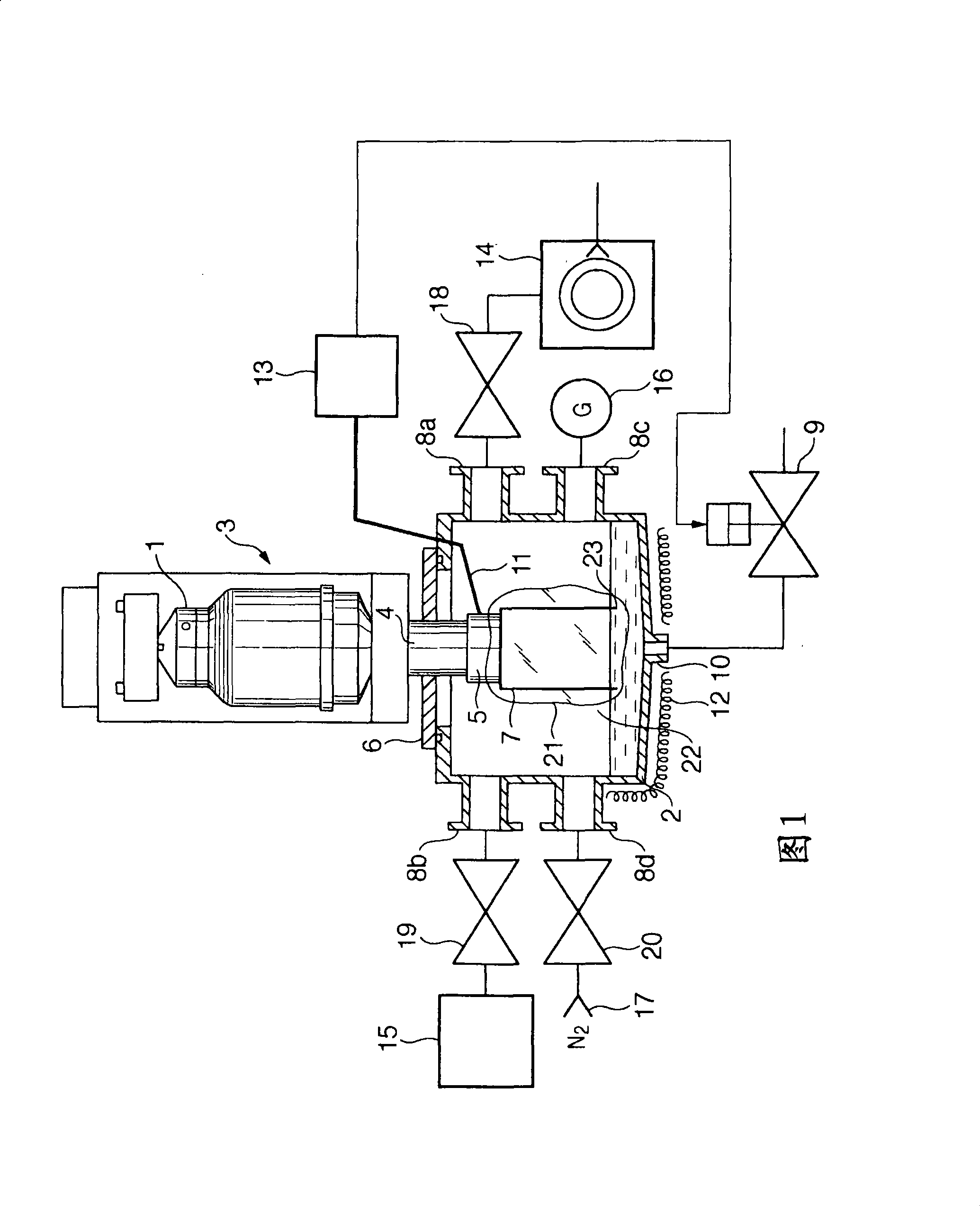
[0024] FIG. 1 is a schematic diagram of an example of a cooling trap unit including a refrigeration structure according to this embodiment, in which a vacuum container is attached to a refrigerator.
[0025] Referring to FIG. 1 , a cooling trap unit 3 in which a vacuum container 2 is attached to a refrigerator 1 such as a vacuum flanged Stirling cycle refrigerator will be explained. The refrigerator 1 used in the present invention may be any one of different types of refrigerators, such as Stirling, GM, pulse tube, Solvay cycle or compressor refrigerators.
[0026] The refrigerator 1 has a heat absorption unit 5 and a vacuum flange 6 attached to the distal end of the cylindrical housing 4 . A cylindrical thin plate called a cooling plate 7 is made of a material having high thermal conductivity such as copper, and the cooling plate 7 is attached to the heat sink unit 5 of the refrigerator 1 in close contact with the heat sink unit 5 on the vacuum side. When the refrigerator 1...
no. 2 example
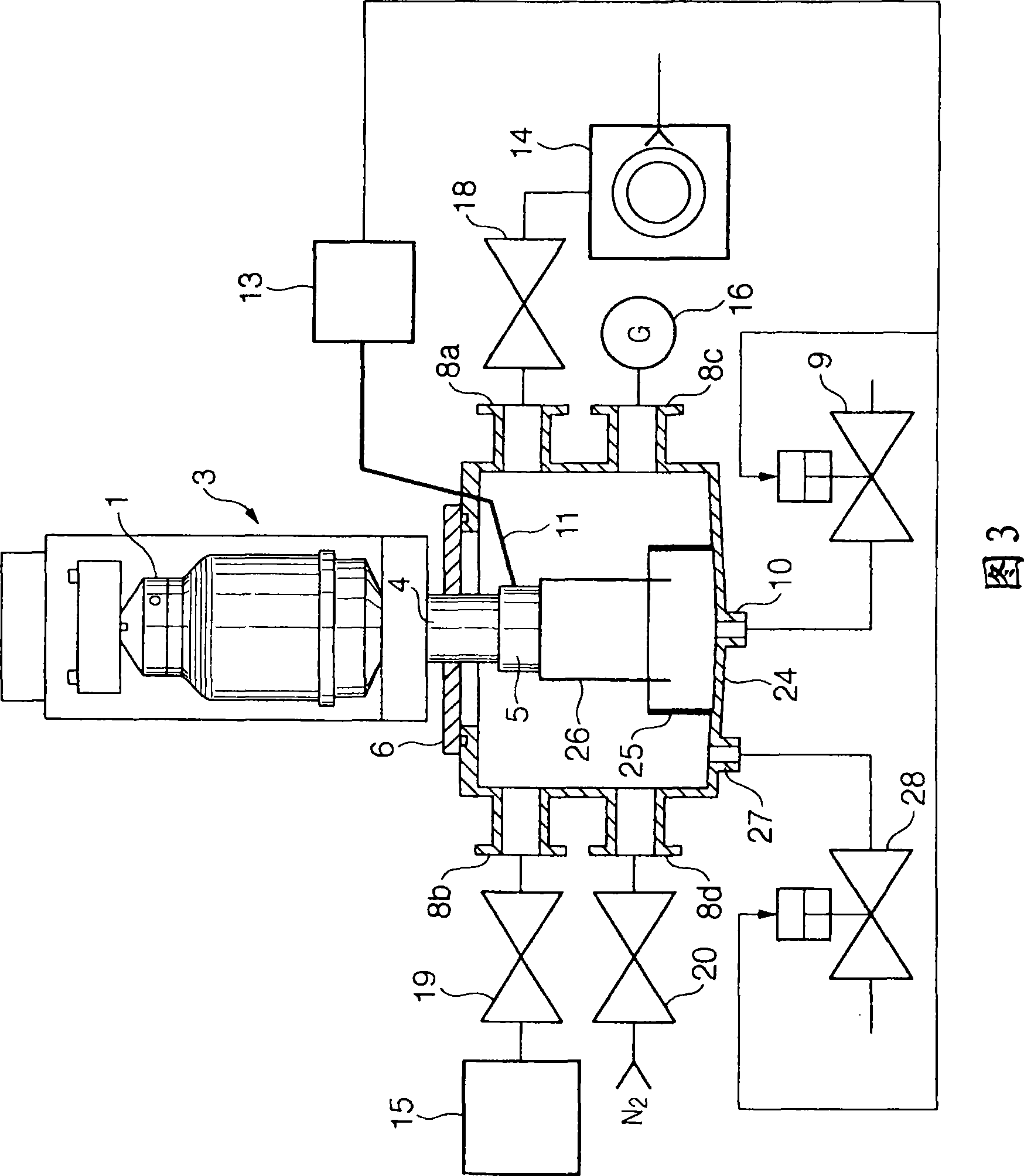
[0040] 3 is a schematic view showing an example of a cooling trap unit including a regenerative structure according to a second embodiment in which a water tank is arranged at the bottom of a vacuum container. Portions common to those in the first embodiment are denoted by the same reference numerals.
[0041] In the arrangement shown in FIG. 3 , the water tank 25 is arranged in the vacuum vessel 24 below the cooling plate 26 and has a bottom area smaller than that of the vacuum vessel 24 . In this arrangement, the water melted during the regeneration process is stored in the water tank 25 and is positioned directly below the cooling plate 26 .
[0042] Water stored in the water tank 25 may be discharged through the drain port 10 . According to this embodiment, the drain port 10 is used as a first drain port to discharge the water stored in the water tank 25 . Therefore, the cooling plate 26 can be in contact with the water stored in the water tank 25 even at the stage where...
no. 3 example
[0045] Figure 4A and 4B is a view showing an example in which groove-like steps 32 are formed in the surface of the cooling plate according to the third embodiment, in which Figure 4A is the plan view of the surface of the cooling plate, and Figure 4B It is a side view of the cooling plate 31 seen from the direction AA'. It should be noted that the cooling plates 7 and 26 of the first and second embodiments are cylindrical, whereas the cooling plate 31 of the third embodiment is a flat cooling plate which is machined into a cylindrical shape. got before.
[0046] Such as Figure 4A and 4B As shown in , the surface of the cooling plate 31 is provided with a plurality of longitudinal groove-like steps 32 , and the steps 32 extend vertically downward from the top along the direction of gravity. Slotted steps are not limited to such as Figure 4A The longitudinal steps are shown extending vertically downwards, but may instead slope from top to bottom (not shown). By forming...
PUM
 Abstract
Description
Claims
Application Information