
Bone screw strength simulation test device

A simulation test, bone screw technology, applied in the direction of measuring device, strength characteristics, using stable tension/pressure test material strength, etc., can solve the problem of joint position deviation, patient pain, and difficulty in grasping the correct drilling position of the bone screw and other problems, to achieve the effect of reasonable structural design, pain reduction, accurate and reasonable fixation

Active Publication Date: 2020-04-17
房财福
View PDF4 Cites 0 Cited by
  • Summary
  • Abstract
  • Description
  • Claims
  • Application Information

AI Technical Summary

Problems solved by technology

[0002] In orthopedic surgery, it is often necessary to use bone screws to connect the steel plate to the injured part of the fracture. Doctors need to take CT films of the injured parts before the operation, and then according to the specific details of the CT films, the doctors operate during the operation based on their own experience, but Sometimes due to the changeable fracture situation, there may be slight deviations in the combination position of the plate and the bone screw during the operation. Especially for doctors who are not experienced enough, it is difficult to grasp the correct drilling position of the bone screw. If the position of the middle bone screw is installed incorrectly, it will bring great pain to the patient and affect the normal growth and recovery of the bone

Method used


Image

  • Bone screw strength simulation test device
  • Bone screw strength simulation test device
  • Bone screw strength simulation test device

Examples


Embodiment Construction

[0023] In order to clearly illustrate the technical features of this solution, the present invention will be described in detail below through specific implementation modes and in conjunction with the accompanying drawings.

[0024] In the following description, many specific details are set forth in order to fully understand the application, but the application can also be implemented in other ways different from those described here, therefore, the protection scope of the application is not limited by the specific details disclosed below. EXAMPLE LIMITATIONS.

[0025] In addition, in the description of the present application, it should be understood that the terms "center", "upper", "lower", "front", "rear", "left", "right", "vertical", "horizontal" ", "Top", "Bottom", "Inner", "Outer", "Axial", "Radial", "Circumferential" and other indicated orientations or positional relationships are based on the orientations or positional relationships shown in the drawings , is only f...


PUM


Abstract

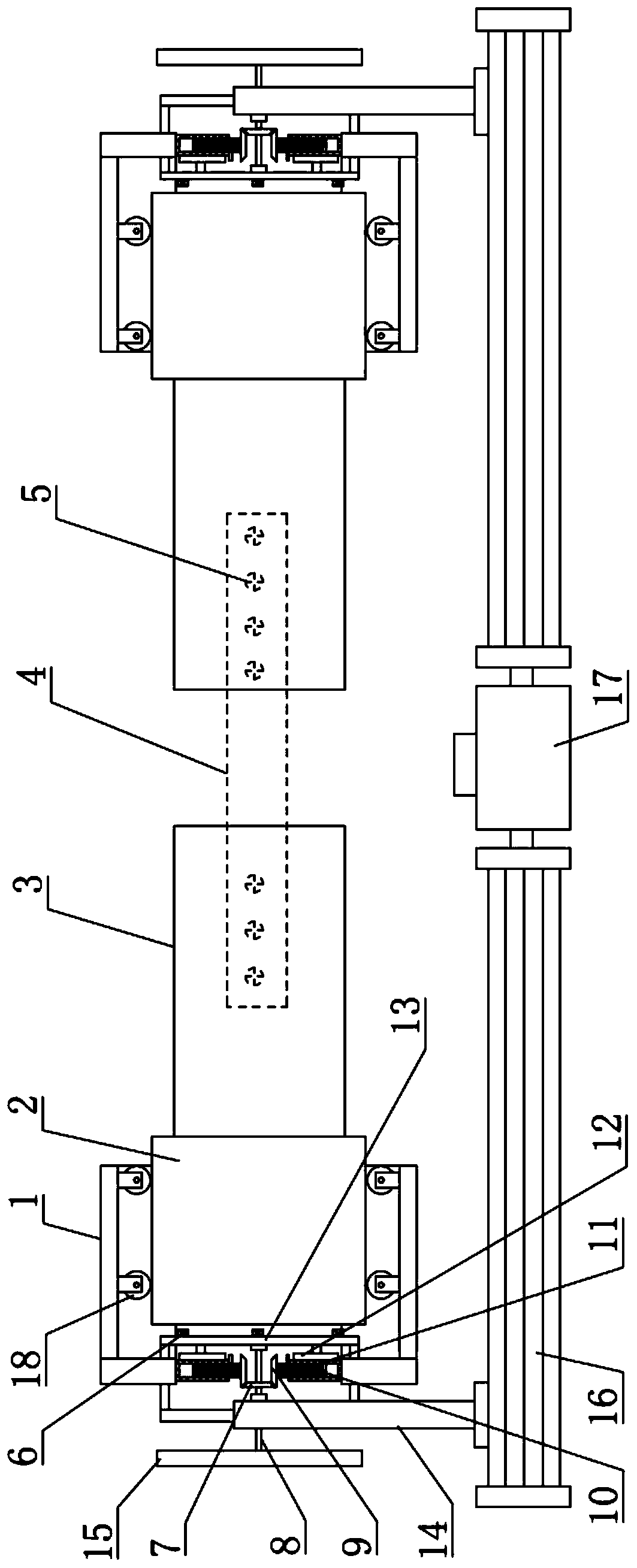
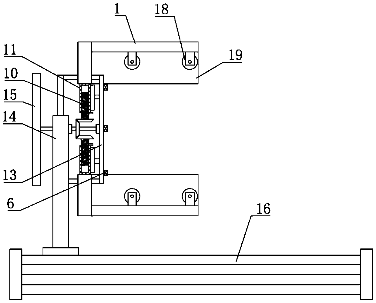
The invention relates to a bone nail strength simulation test device. The bone nail strength simulation test device comprises a fixing device and a displacement device; the fixing device comprises twofixing parts arranged symmetrically; the fixing parts are provided with fixing planes arranged parallel to each other; the fixing parts are connected to a driving mechanism so that the two fixing parts move close to each other or away from each other in a straight line, so as to clamp and fix a guiding part; the guiding part has a fixing plane corresponding to the fixing part; the guiding part isconnected to a simulation part; the simulation part is adapted to simulate a human skeleton; and the displacement device is connected to the fixing device, so that the fixing device moves along the axial direction of the simulation part. The invention has a reasonable structural design; and a doctor can simulate the connection position of a steel plate and the bone nail according to the specificdetails of the CT shooting, and make a preliminary simulation of the force situation of the nail, so that the fixation of the steel plate and the bone nail is more accurate and reasonable, the pain caused by the bone nail and the steel plate after connecting is reduced, and the fracture position is accurately guided and fixed.

Description

technical field [0001] The invention relates to a strength simulation test device for bone nails. Background technique [0002] In orthopedic surgery, it is often necessary to use bone screws to connect the steel plate to the injured part of the fracture. Doctors need to take CT films of the injured parts before the operation, and then according to the specific details of the CT films, the doctors operate during the operation based on their own experience, but Sometimes due to the changeable fracture situation, there may be slight deviations in the combination position of the plate and the bone screw during the operation. Especially for doctors who are not experienced enough, it is difficult to grasp the correct drilling position of the bone screw. If the position of the bone screw is installed incorrectly, it will cause great pain to the patient and affect the normal growth and recovery of the bone. Contents of the invention [0003] The invention provides a strength sim...

Claims


Application Information

Patent Timeline
Patent Type & Authority Patents(China)
IPC IPC(8): G01N3/08G01N3/04
CPCG01N3/04G01N3/08
Inventor 房财福
Owner 房财福
Learn More