Proximal humerus intramedullary nail internal fixation system

A fixation system and intramedullary nail technology, applied in the field of medical equipment, can solve the problems of long learning curve of operation technology, difficult operation, damage to the rotator cuff, etc., and achieve the effect of reducing the learning curve, easy operation reset, and simplified operation

Pending Publication Date: 2021-08-20
DABO MEDICAL TECH CO LTD +1
View PDF0 Cites 0 Cited by
  • Summary
  • Abstract
  • Description
  • Claims
  • Application Information

AI Technical Summary

Problems solved by technology

[0003] Locking plates are effective in treating displaced proximal humerus fractures, but there are: 1. Eccentric fixation, large fixation force arm, and poor resistance to varus stress
2. The peeling range is large, which affects the blood supply
3. It is difficult to fix the screw to the tuberosity fracture
4. Disadvantages of many complications such as varus deformity, screw cutting out and humeral head necrosis after operation
[0004] The proximal humeral intramedullary nail has obvious advantages over plate and screw internal fixation. In recent years, doctors have paid more and more attention to it in clinical treatment, but it faces several difficulties: 1. The learning curve of operation technology is too long, which requires a lot of surgical technology.
Locking plates are often approached through the deltoid-pectoralis major muscle space, and the operation is easier under direct vision. Intramedullary nails are closed and reduced, approached from the anterolateral small incision of the acromion, and then internal fixation is used after reduction. Fixed, the operation is difficult and there are certain requirements for surgical techniques
2. Difficult reduction, closed reduction with intramedullary nails often cannot achieve anatomical reduction of fractures
3. The existing fixation method will damage the rotator cuff and damage the articular surface

Method used


Image

  • Proximal humerus intramedullary nail internal fixation system
  • Proximal humerus intramedullary nail internal fixation system
  • Proximal humerus intramedullary nail internal fixation system

Examples


Embodiment 1

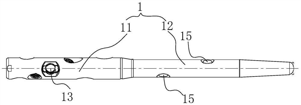
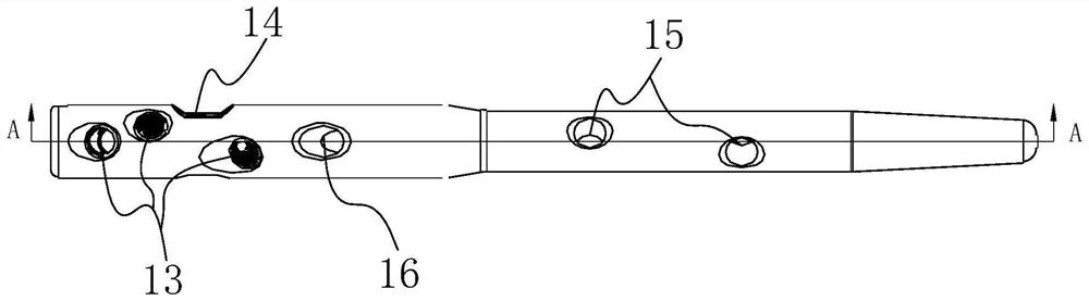
[0045] The main nail 1 of the humeral intramedullary nail is a short nail with a length of 160mm-210mm; the number of the transverse locking nail holes 13 is three, and the axial extension direction points to the posterior medial side of the humeral head; the functional hole 16 is the central axis As for the oblique holes extending upward, the number of the common nail holes 15 is two. The oblique hole passes through a 4.0 ordinary nail to fix the calcar humerus.

Embodiment 2

[0047] The main nail 1 of the humeral intramedullary nail is a long nail with a length of 210mm-285mm; the number of the transverse locking nail holes 13 is three, and the axial extension direction points to the posterior medial side of the humeral head; the functional hole 16 is for pressurization holes, the number of the common nail holes 15 is three. The pressurization hole can be pressurized through a 4.0 ordinary nail.

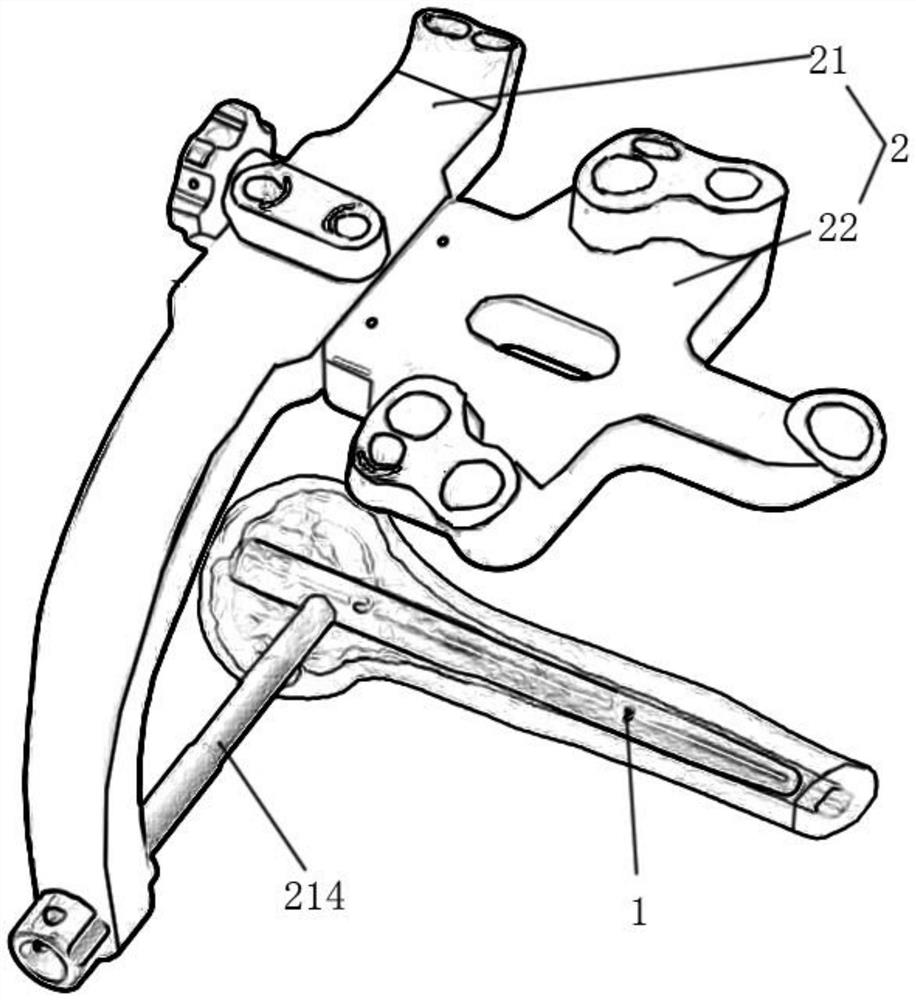
[0048] Further, two proximal aiming holes 216 are distributed in the middle section of the transverse bar 212, and two are distributed at the end of the transverse bar 212, and the two proximal aiming holes 216 located in the middle section of the transverse bar 212 and the The two proximal aiming holes 216 at the end of the transverse rod 212 are distributed along the distal and proximal directions. The proximal aiming hole corresponds to the horizontal locking nail hole, which is used to guide the installation of the locking nail.

[0049] Further, tw...


PUM


Abstract

The invention relates to a proximal humerus intramedullary nail internal fixation system. The system mainly comprises a humeral intramedullary nail main nail, an aiming frame, a fixing plate and lock nail sets of different specifications, the humeral intramedullary nail main nail is arranged in the humerus, the fixing plate and the lock nail sets are installed and fixed by matching with the aiming frame, and therefore humerus restoration is achieved. According to the present invention, the operation of humerus reduction can be simplified, the learning curve is reduced, and damage to the rotator cuff and damage to the articular surface can be avoided.

Description

technical field [0001] The invention relates to the field of medical equipment, in particular to a proximal humeral intramedullary nail internal fixation system. Background technique [0002] Fractures of the proximal humerus account for about 5% of all fractures in adults and are the second most common upper extremity fracture in the elderly. The occurrence of proximal humerus fractures is obviously related to osteoporosis. With the development of society and economy and the prolongation of life expectancy, the incidence of proximal humerus fractures tends to increase, which is a difficult point in trauma orthopedics treatment. Diagnosis of proximal humerus fractures is not difficult with imaging examinations such as X-rays. At present, the Neer classification is commonly used clinically to classify proximal humeral fractures. Conservative treatment can be used for patients with small displacement and some patients with obvious contraindications to surgery. Surgical treat...

Claims


Application Information

Patent Timeline
Patent Type & Authority Applications(China)
IPC IPC(8): A61B17/72A61B17/80A61B17/90
CPCA61B17/725A61B17/8057A61B17/808A61B17/88
Inventor 付中国刘崇兵李俊峰林煜江道海邹泽鹏
Owner DABO MEDICAL TECH CO LTD
Why Eureka
Try Eureka