Opposite horn producing device based on automatic induction pressure gauge machine

An automatic induction and production device technology, applied in metal processing, metal processing equipment, manufacturing tools, etc., can solve the problems of high cost, reduced productivity, large installation deviation, etc., and achieve the effect of convenient operation, reasonable setting, and smooth connection.

Inactive Publication Date: 2018-03-06
WUZHOU HENGSHENG ELECTRONICS
View PDF8 Cites 0 Cited by
  • Summary
  • Abstract
  • Description
  • Claims
  • Application Information

AI Technical Summary

Problems solved by technology

The large-scale use of speakers in real life is faced with mass production, and in the production process of speakers, mechanical equipment is needed, among which the assembly of the upper and lower shells of the speakers is a very important part, and the automatic induction pressure gauge machine is Provide angle support to install between the upper and lower shells of the horn, but in the current installation of the upper and lower shells of the horn, due to the high cost of the automatic induction pressure gauge machine, most of them still choose the construction personnel to visually measure the angle, which also This has resulted in a certain degree of reduced productivity and large installation deviations. Therefore, we propose a horn production device based on an automatic induction pressure gauge machine to solve the above problems.

Method used


Image

  • Opposite horn producing device based on automatic induction pressure gauge machine
  • Opposite horn producing device based on automatic induction pressure gauge machine

Examples


Embodiment Construction

[0015] The following will clearly and completely describe the technical solutions in the embodiments of the present invention with reference to the accompanying drawings in the embodiments of the present invention. Obviously, the described embodiments are only some, not all, embodiments of the present invention. Based on the embodiments of the present invention, all other embodiments obtained by persons of ordinary skill in the art without making creative efforts belong to the protection scope of the present invention.

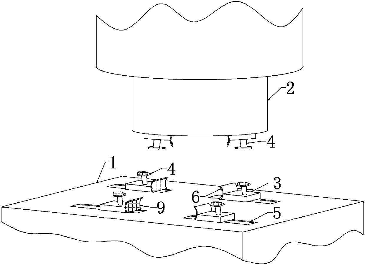
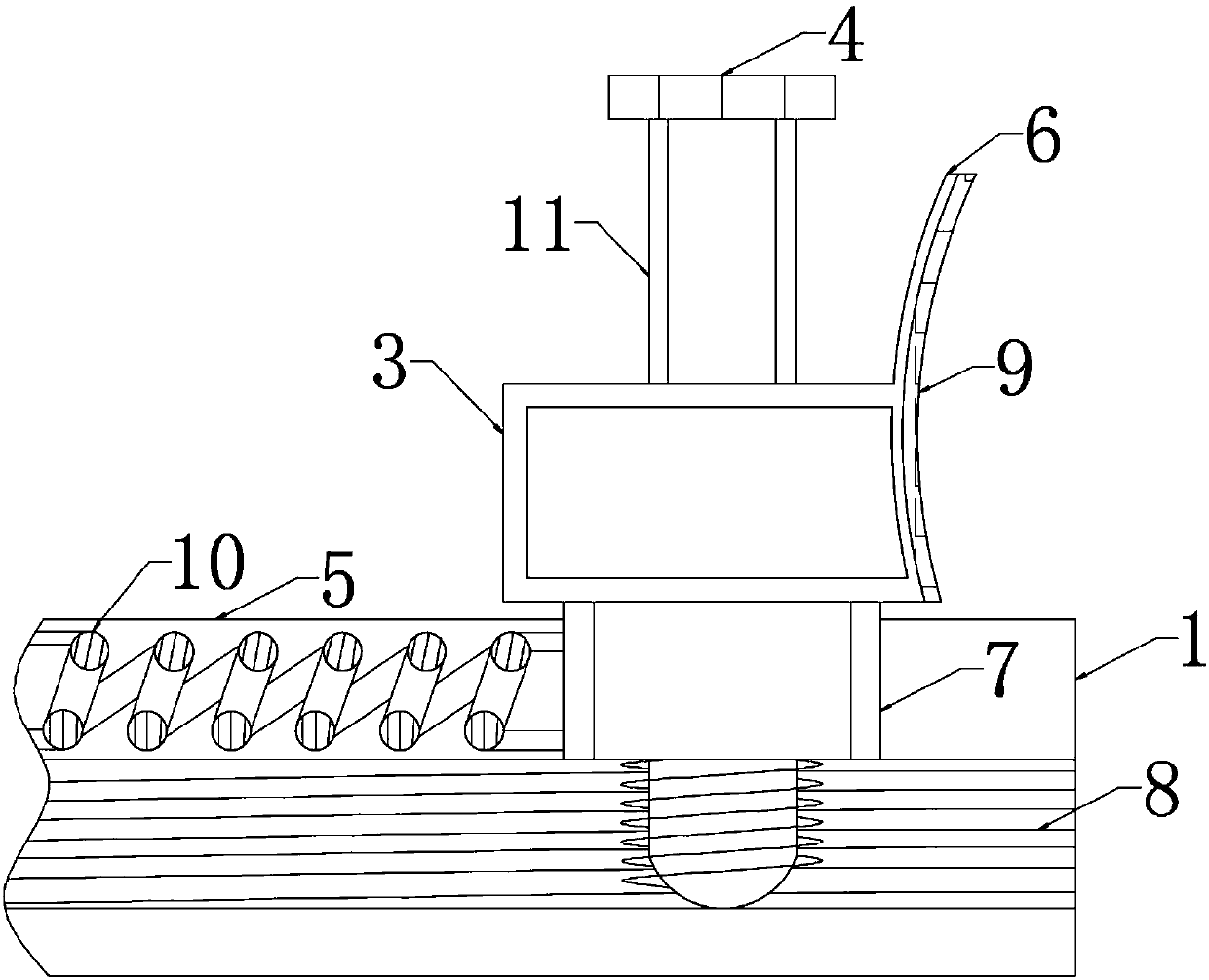
[0016] see Figure 1-2 , the present invention provides a technical solution: a speaker production device based on an automatic induction pressure gauge machine, including a worktable 1 and a pressing device 2, the pressing device 2 is located at the upper end of the workbench 1, and the upper end surface of the workbench 1 A movable block and a fixed chute 5 are arranged on the top, the movable block includes an upper movable block 3 and a lower movable block...


PUM


Abstract

The invention provides an opposite horn producing device based on an automatic induction pressure gauge machine. The opposite horn producing device based on the automatic induction pressure gauge machine comprises a workbench and a press-fitting device. According to the opposite horn producing device based on the automatic induction pressure gauge machine, due to the fact that four upper movable blocks are arranged in a radial shape based on the press-fitting device; four lower movable blocks are correspondingly arranged on the lower end face of the press-fitting device, the novel structure ismade distinct, and combined fixing for a horn is more reasonable; due to the fact that a fixing plate is arranged into an arc shape with an opening facing the press-fitting device; a fixing block isin a rubber arc shape equal to that of the fixing plate, and the fixing block and the fixing plate are fixedly connected; when the novel structure works, fixing of the horn has certain buffering performance, and no damage can be caused; due to the fact that the sum of the length of the lower movable blocks and the maximum length of a built-in spring is equal to 2/3 of the length of a fixed slide groove, a positioning rod is located at the upper ends of the upper movable blocks, and a threaded rod is arranged at the lower ends of the lower movable blocks, when the novel structure works, an upper shell and a lower shell of the horn are connected smoothly.

Description

technical field [0001] The invention relates to the technical field related to machinery, in particular to a horn production device based on an automatic induction pressure gauge machine. Background technique [0002] In today's high-tech society, the use of speakers can be seen everywhere. It can also be said that speakers are an indispensable part of today's society. The large-scale use of speakers in real life is faced with mass production, and in the production process of speakers, mechanical equipment is needed, among which the assembly of the upper and lower shells of the speakers is a very important part, and the automatic induction pressure gauge machine is Provide angle support to install between the upper and lower shells of the horn, but in the current installation of the upper and lower shells of the horn, due to the high cost of the automatic induction pressure gauge machine, most of them still choose the construction personnel to visually measure the angle, whi...

Claims


Application Information

Patent Timeline
Patent Type & Authority Applications(China)
IPC IPC(8): B23P19/02B23P19/00
CPCB23P19/02B23P19/006
Inventor 甘霖罗荣金于代勇陈朝银吴立忠
Owner WUZHOU HENGSHENG ELECTRONICS
Why Eureka
Try Eureka