Dry-type transformer

A dry-type transformer and transformer technology, applied in the direction of transformer/inductor housing, transformer/inductor cooling, transformer/inductor components, etc., can solve problems such as high temperature and failure, and achieve the effect of improving firmness

Active Publication Date: 2019-08-30
GUANGZHOU GAOTIE MEASUREMENT & TESTING CO LTD
7 Cites 3 Cited by

AI-Extracted Technical Summary

Problems solved by technology

[0004] Aiming at the deficiencies of the prior art, the purpose of the present invention is to provide a dry-type transfor...

Method used

As shown in Figure 6, the surface of base plate 3 is penetrated and provided with second threaded hole 301, and the both sides of base plate are provided with mutually symmetrical clip bar 31, and clip bar 31 is engaged with limit groove 22 and is fixed, and The bottom plate 3 completely covers the bottom of the casing 2 , and the second threaded hole 301 can also play a role of ventilation and heat dissipation.
Locking bolts 221 are evenly distributed on the upper surface where the limit groove 22 is located, and the locking bolts 221 run through the bottom of the casing 2 and the second threaded hole 301 on the surface of the base plate 3 at the same time, and the locking bolts 221 are diameters at both ends. The bolt-like structure with a diameter larger than the middle part can effectively realize the fixed connection between the bottom plate 3 and the casing 2 .
The first threaded hole 101 on the bottom pole 11 of the transformer body 1 and the second threaded hole 301 on the surface of the base plate 3 are fastened by bolts, and the second threaded hole 301 is evenly distributed, and the second threaded hole 301 i...

Abstract

The invention discloses a dry-type transformer. The dry-type transformer comprises a transformer body, a housing, a bottom plate and a fan, wherein the transformer body is formed by a plurality of groups of encapsulated windings in an array mode, a supporting rod is arranged at the bottom of the transformer body and allow the encapsulated windings in each group to connect with each other, the supporting rod is arranged in a crossed mode, and first threaded holes penetrate the supporting rod; the transformer body is integrally arranged in the cavity of the housing, and the bottom of the transformer body is fixedly positioned with the bottom plate, and meanwhile, the transformer body is arranged in the housing through the fan, the whole device achieves dispelling the heat in the transformerbody, and the graphite material of housing side is protruding simultaneously, and the heat from the housing is diffused quickly, and the protrusion of the array distribution can reduce the air great dust entering the inner wall of the housing through air vents.

Application Domain

Transformers/reacts mounting/support/suspensionTransformers/inductances cooling +1

Technology Topic

TransformerGraphite +1

Image

  • Dry-type transformer
  • Dry-type transformer
  • Dry-type transformer

Examples

  • Experimental program(1)

Example Embodiment

[0027] The technical solutions in the embodiments of the present invention will be clearly and completely described below in conjunction with the accompanying drawings in the embodiments of the present invention. Obviously, the described embodiments are only a part of the embodiments of the present invention, rather than all the embodiments. Based on the embodiments of the present invention, all other embodiments obtained by those of ordinary skill in the art without creative work shall fall within the protection scope of the present invention.
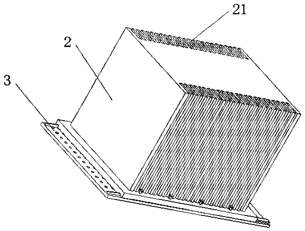
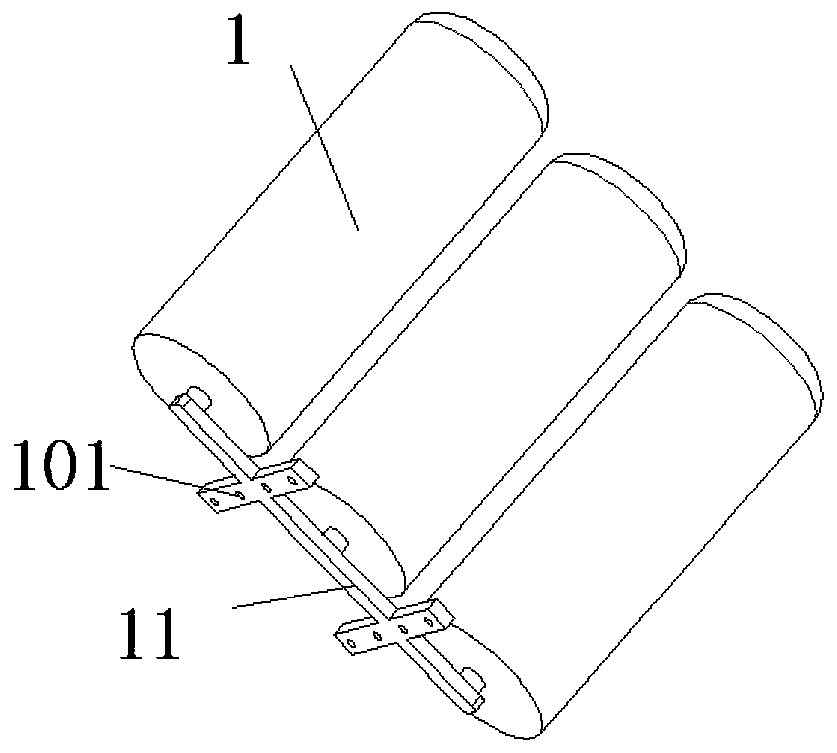
[0028] Such as figure 1 , figure 2 , image 3 As shown, the embodiment of the present invention provides a dry-type transformer, including a transformer body 1, a cover 2, a bottom plate 3, and a fan 4. The transformer body 1 is composed of multiple sets of encapsulated winding arrays and generally selects 3 sets of arrays, and the transformer The bottom of the body 1 is provided with a supporting rod 11, which connects each group of encapsulated windings to each other, and the supporting rods 11 are arranged in a cross, so that the supporting rod 11 as a whole is sufficient to support the transformer body 1, and the supporting rod 11 penetrates A threaded hole 101.
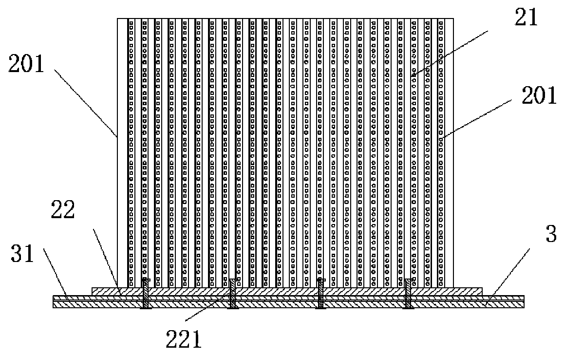
[0029] Such as Figure 4 , 5 As shown, the bottom of the casing 2 has an open cavity structure, and the outer walls on both sides of the casing 2 are symmetrically provided with convex edges 21 protruding outward. The protrusions 21 are made of graphite and are integrally formed with the outer walls on both sides of the casing 2. It is distributed in an array along the outer walls on both sides of the casing 2. Vent holes 201 are distributed along the convex edge 21 and the outer wall on both sides of the casing 2. The ventilation holes 201 on the outer wall of the casing 2 communicate with the inner cavity. 2 The two sides of the bottom of the housing 2 are symmetrically provided with a positioning groove 22 along the array direction of the convex edge 21.
[0030] Such as Image 6 As shown, the surface of the bottom plate 3 is provided with a second threaded hole 301, and symmetrical clamping strips 31 are provided on both sides of the bottom plate. The clamping strips 31 are locked and fixed with the limiting groove 22, and the bottom plate 3 completely covers the cover. At the bottom of the shell 2, the second threaded hole 301 can also provide ventilation and heat dissipation.
[0031] The first threaded hole 101 on the strut 11 at the bottom of the transformer body 1 and the second threaded hole 301 on the surface of the bottom plate 3 are fastened by bolts, and the second threaded holes 301 are evenly distributed. Adjust the first threaded holes appropriately according to the location requirements. In the connection position relationship between 101 and the second threaded hole 301, the transformer body 1 is placed in the cavity of the casing 2 as a whole to prevent the bottom plate 3 from shaking when being fixed.
[0032] The upper surface of the limiting groove 22 is evenly distributed with locking bolts 221. The locking bolts 221 pass through the bottom of the casing 2 and the second threaded holes 301 on the surface of the bottom plate 3 at the same time. The diameters of the locking bolts 221 are larger than the middle diameter at both ends The bolt-like structure can effectively realize the fixed connection between the bottom plate 3 and the cover 2.
[0033] Such as Figure 7 As shown, the fan 4 includes a wind hood 41 and a wind blade 42 arranged at the bottom of the outer casing 41. The wind hood 41 has a circular structure as a whole with a cavity in the middle. The outer wall where the wind hood 41 is located is a hollow structure. It is fixedly connected to the top of the cavity structure of the casing 2. The top of the fan 4 provides power supply through a power connection line, and the power connection line runs through the top of the casing 2 to communicate with an external power source.
[0034] When in use, the fan 4 can effectively realize air circulation in the cavity of the casing 2 and avoid damage to the transformer body 1 caused by excessive local temperature. At the same time, the ventilation holes 201 on the outer wall of the casing 2 communicate with the internal cavity to effectively dissipate heat, and the array of protrusions 21 can effectively absorb the heat emitted through the ventilation holes 201 on the outer wall of the casing 2, and The purpose of rapid cooling can be achieved, and the protrusions 21 are relatively densely distributed, and the adjacent protrusions 21 are also provided with vent holes 201 to attach external dust, so as to avoid entering the interior through the outer wall of the casing 2 and causing Damage to the transformer body 1.
[0035] In the description of this specification, the description with reference to the terms "one embodiment", "example", "specific example", etc. means that the specific feature, structure, material or characteristic described in combination with the embodiment or example is included in at least the present invention. In one embodiment or example. In this specification, the schematic representations of the above terms do not necessarily refer to the same embodiment or example. Moreover, the described specific features, structures, materials or characteristics may be combined in any one or more embodiments or examples in a suitable manner.
[0036] The above shows and describes the basic principles, main features and advantages of the present invention. Those skilled in the industry should understand that the present invention is not limited by the foregoing embodiments. The foregoing embodiments and descriptions only illustrate the principles of the present invention. Without departing from the spirit and scope of the present invention, the present invention may have Various changes and improvements, these changes and improvements fall within the scope of the claimed invention.

PUM

no PUM

Description & Claims & Application Information

We can also present the details of the Description, Claims and Application information to help users get a comprehensive understanding of the technical details of the patent, such as background art, summary of invention, brief description of drawings, description of embodiments, and other original content. On the other hand, users can also determine the specific scope of protection of the technology through the list of claims; as well as understand the changes in the life cycle of the technology with the presentation of the patent timeline. Login to view more.

Similar technology patents

Ferromagnetic composite filter paper for oil filter and preparation method of composite filter paper

InactiveCN103966908AImprove firmnessGood water resistance and oil resistance
Owner:ANHUI PHOENIX INT CO LTD

Safe cable

PendingCN108399969Aprotect the working environmentImprove firmness
Owner:FUJIAN TONGYU CABLES

Compression-resisting packaging box

InactiveCN106915529AImprove firmnesssave material
Owner:BAIXIN LIREN TIANJIN TECH CO LTD

Packing bag automatic opening device

PendingCN106742311AImprove firmness
Owner:中铁建电气化局集团轨道交通器材有限公司

Classification and recommendation of technical efficacy words

  • Improve firmness

High-speed electric connector and signal module thereof, and molding method of signal module

ActiveCN106207569AImprove firmnessSolve easy deformation
Owner:CHINA AVIATION OPTICAL-ELECTRICAL TECH CO LTD

Method for welding aluminum materials

ActiveCN101648312Aadd depthImprove firmness
Owner:KONFOONG MATERIALS INTERNATIONAL CO LTD

Environment-friendly PU leather

InactiveCN104372680AGood moisture permeability and air permeabilityImprove firmness
Owner:ZHEJIANG JINSHANG SYNTHETIC LEATHER

Drilling tool for architectural section

Owner:芜湖瑞德机械科技有限公司
Why Eureka
Try Eureka