Outer rotor structure

An external rotor, integrated technology, applied in the direction of casing/housing/support, electrical components, electromechanical devices, etc., can solve the problem that the motor magnetic field cannot be greatly utilized, the stator core yoke is reduced, the stator core yoke is small, etc. problem, to achieve the effect of improving motor efficiency, simplifying the processing procedure, and increasing the width of the yoke

Inactive Publication Date: 2019-08-30
FANS TECH ELECTRIC CO LTD
View PDF6 Cites 0 Cited by
  • Summary
  • Abstract
  • Description
  • Claims
  • Application Information

AI Technical Summary

Problems solved by technology

[0002] The existing outer rotor structure is that the inner stator is press-fitted on the base, which reduces the yoke of the stator core of the inner stator and cannot greatly utilize the magnetic field of the motor; since the inner stator is press-fitted on the outer diameter of the base, The bearing is installed on the inner diameter of the base, and the shaft is tightly fitted in the bearing. The concentricity between the shaft and the outer diameter of the stator core is poor due to multiple processing and cooperation. In order to ensure better concentricity, the outer diameter of the stator core often needs to be adjusted. Subsequent grinding to ensure concentricity
[0003] Existing technologies such as the invention patent CN201038880Y outer rotor motor, the invention includes an outer rotor, an inner stator, the shaft is tightly fitted on the outer rotor, a bearing is installed between the outer rotor and the shaft, and elastic wave washers, Washer, spacer, the elastic wave washer is pressed on the bearing, the washer is installed between the outer rotor and the shaft and connected with the elastic wave washer, and the spacer connected with the washer is pressed on the shaft through the locking bolt; through this structure Design, the inner ring of the shaft and the bearing is a loose fit, and the axial force is applied to the inner ring of the bearing with the lock nut through the washer and the washer, so that the inner ring of the bearing, the shaft and the outer rotor are tightly pressed together to rotate without relative sliding phenomenon, but the bearings of the outer rotor motor are still arranged at both ends of the base, and the inner stator needs to be press-fitted on the base, resulting in a small yoke of the stator core, which cannot greatly utilize the magnetic field of the motor, and in order to ensure concentricity Still need to carry out tedious processing steps

Method used


Image

  • Outer rotor structure
  • Outer rotor structure

Examples


Embodiment 1

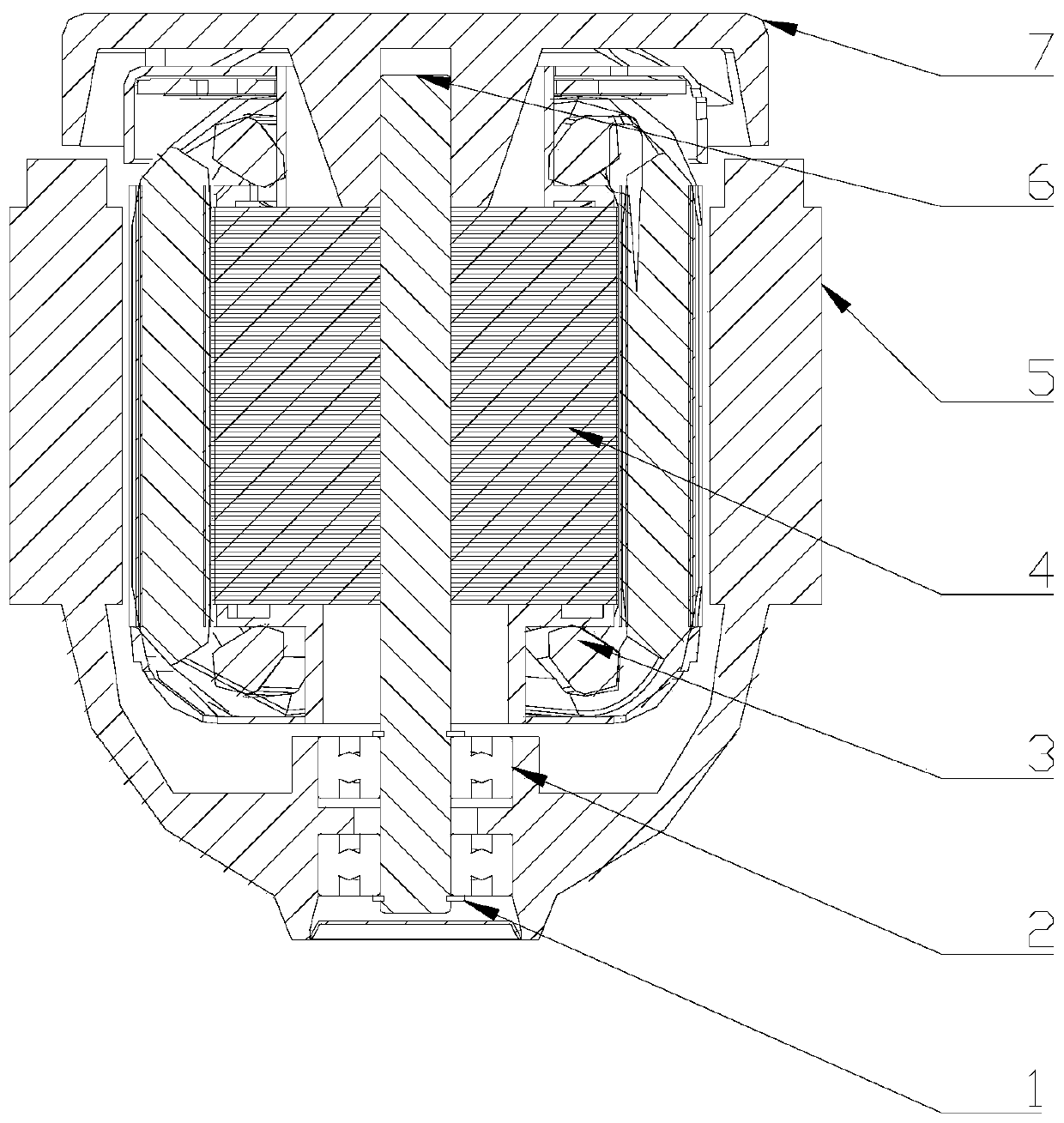
[0020] refer to Figure 1-2 , this embodiment discloses an outer rotor structure, including a first end cover 7, a shaft 6, an outer rotor 5, a stator core 4, a winding 3, two bearings 2 and two snap springs 1; the outer rotor 5 The integrally formed outer rotor 5 simplifies the assembly process of an end cover and the outer rotor. One axial end of the outer rotor 5 is provided with two concave cavities, that is, bearing chambers for installing the bearing 2. The one The concave cavity faces the inside of the outer rotor 5, and the other cavity faces the outside of the outer rotor 5. The two concave cavities are separated by a raised structure, and the other axial end of the outer rotor 5 is Fully open structure, the middle part of the outer rotor 5 is connected with the end with a concave cavity through an arc structure, and a cavity is formed inside the outer rotor 5 for installing other components. The outer walls of the outer rings of the two bearings 2 are interference f...

Embodiment 2

[0024] This embodiment discloses an outer rotor structure, including a first end cover 7, a second end cover, a shaft 6, an outer rotor 5, a stator core 4, a winding 3, two bearings 2 and two retaining springs 1; The outer rotor 5 of the embodiment is a split structure, that is, the second end cover and the outer rotor 5 are detachably assembled, and the second end cover is made of aluminum, which facilitates the second end cover and the outer rotor 5 The assembly of the outer rotor 5 is also convenient for the assembly of other components inside; the second end cover is provided with two cavities, that is, the bearing chamber for installing the bearing 2, and the one cavity faces the outer rotor 5 The other concave cavity faces the outside of the outer rotor 5, and the two concave cavities are separated by a raised structure. The axial ends of the outer rotor 5 are fully open structures, and the second The end cover is fixedly connected to one end of the outer rotor 5, the ou...

Embodiment 3

[0028]This embodiment discloses an outer rotor structure, including a first end cover 7, a second end cover, a shaft 6, an outer rotor 5, a stator core 4, a winding 3, two bearings 2 and two retaining springs 1; The outer rotor 5 of the embodiment is a split structure, that is, the second end cover and the outer rotor 5 are detachably assembled, the material of the second end cover is iron, and the axial ends of the outer rotor 5 are full Open structure, the second end cover is tightly fitted outside the outer rotor 5, that is, the outer rotor 5 is surrounded except for one end in the axial direction. Since the material of the second end cover is iron, Such setting can increase the magnetic conduction area. When increasing the width of the yoke of the stator core 4 to increase the magnetic field, the magnetic field can be further increased, thereby further improving the efficiency of the motor. Two recesses are arranged in the second end cover. cavity, that is, the bearing cha...


PUM


Abstract

The invention discloses an outer rotor structure which includes an outer rotor, an inner stator, a shaft, a first end cover, a second end cover and a plurality of bearings, wherein the outer rotor sleeves the outside of the inner stator; the first end cover and the second end cover cover the two ends of the outer rotor respectively; the shaft passes through the first end cover, the inner stator and the second end cover; the second end cover is fixedly connected with the outer rotor, and is provided therein with a plurality of cavities corresponding to the plurality of bearings one to one; theouter walls of the outer rings of the plurality of bearing are in interference fit with the inner walls of the cavities respectively; the outer wall of one end of the shaft is in interference fit withthe inner walls of the inner rings of all the bearings; and the outer wall of the other end of the shaft is in interference fit with the first end cover. Since the bearings are disposed in the secondend cover, the shaft can be in interference fit with the inner stator, thereby ensuring the concentricity of the shaft and the inner stator, simplifying subsequent processing processes, increasing the yoke width of the inner stator, increasing the magnetic field and improving the efficiency of the motor.

Description

technical field [0001] The invention relates to the field of motors, in particular to an outer rotor structure. Background technique [0002] The existing outer rotor structure is that the inner stator is press-fitted on the base, which reduces the yoke of the stator core of the inner stator and cannot greatly utilize the magnetic field of the motor; since the inner stator is press-fitted on the outer diameter of the base, The bearing is installed on the inner diameter of the base, and the shaft is tightly fitted in the bearing. The concentricity between the shaft and the outer diameter of the stator core is poor due to multiple processing and cooperation. In order to better ensure the concentricity, the outer diameter of the stator core often needs to be adjusted Subsequent grinding process to ensure the concentricity problem. [0003] Existing technologies such as the invention patent CN201038880Y outer rotor motor, the invention includes an outer rotor, an inner stator, ...

Claims


Application Information

Patent Timeline
IPC IPC(8): H02K5/16
CPCH02K5/165
Inventor 叶兴文金玉龙
Owner FANS TECH ELECTRIC CO LTD
Why Eureka
Try Eureka