Stripping machine capable of unifying specifications of rods

A peeling machine and specification technology, which is applied to other manufacturing equipment/tools, sawing devices, metal sawing equipment, etc., can solve the problems of wasting manpower and material resources, can not guarantee the consistency of bar material, and cannot cut bar material, so as to save manpower Material resources, convenient processing procedures, and the effect of ensuring production efficiency

Active Publication Date: 2017-12-22
TAICANG BEST MECHANICAL EQUIP
View PDF6 Cites 5 Cited by
  • Summary
  • Abstract
  • Description
  • Claims
  • Application Information

AI Technical Summary

Problems solved by technology

[0005] 1. Most of the current peeling machines cannot cut the bar material, and need additional processes and equipment to cut the bar material before entering the next process, and the extra cutting process requires the participation of personnel, which wastes manpower an

Method used


Image

  • Stripping machine capable of unifying specifications of rods
  • Stripping machine capable of unifying specifications of rods
  • Stripping machine capable of unifying specifications of rods

Examples


Example Embodiment

[0041] Example 1

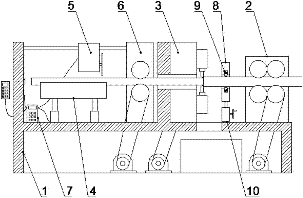
[0042] like figure 1 A peeling machine that can unify the specifications of bar stock is shown, including: a frame 1, a feeding support mechanism 2, a positioning mechanism, a peeling mechanism 3 and an automatic cutting mechanism, and one side of the frame 1 is provided with a feeding support Mechanism 2, the frame 1 is sequentially provided with a positioning mechanism, a peeling mechanism 3 and an automatic cutting mechanism; the automatic cutting mechanism includes a lifting platform 4, a cutting mechanism 5, a cutting feeding mechanism 6 and a control mechanism 7, The lifting platform 4 is arranged on the frame 1, a cutting mechanism 5 is arranged above the lifting platform 4, a control mechanism 7 for determining the length of the cutting material is arranged on the cutting mechanism 5, and a side of the peeling mechanism 3 is arranged There is a cutting feed mechanism 6.

Example Embodiment

[0043] Example 2

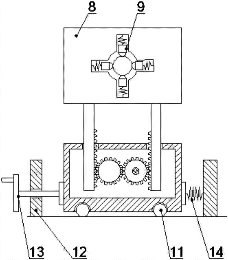
[0044] like figure 2 A peeling machine that can unify the specifications of bar stock is shown, including: a frame 1, a feeding support mechanism 2, a positioning mechanism, a peeling mechanism 3 and an automatic cutting mechanism, and one side of the frame 1 is provided with a feeding support Mechanism 2, the frame 1 is sequentially provided with a positioning mechanism, a peeling mechanism 3 and an automatic cutting mechanism; the automatic cutting mechanism includes a lifting platform 4, a cutting mechanism 5, a cutting feeding mechanism 6 and a control mechanism 7, The lifting platform 4 is arranged on the frame 1, a cutting mechanism 5 is arranged above the lifting platform 4, a control mechanism 7 for determining the length of the cutting material is arranged on the cutting mechanism 5, and a side of the peeling mechanism 3 is arranged There is a cutting feed mechanism 6.

[0045] The positioning mechanism described in this embodiment includes a pos...

Example Embodiment

[0047] Example 3

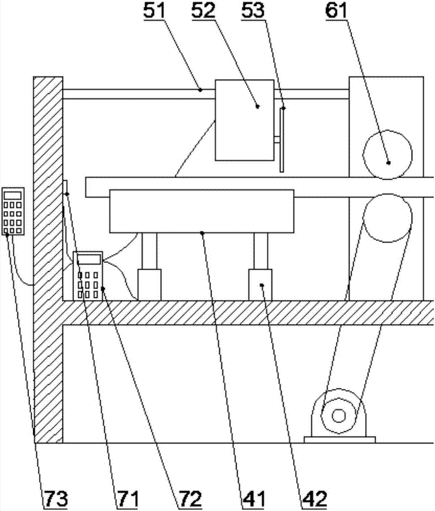
[0048] like image 3 A peeling machine that can unify the specifications of bar stock is shown, including: a frame 1, a feeding support mechanism 2, a positioning mechanism, a peeling mechanism 3 and an automatic cutting mechanism, and one side of the frame 1 is provided with a feeding support Mechanism 2, the frame 1 is sequentially provided with a positioning mechanism, a peeling mechanism 3 and an automatic cutting mechanism; the automatic cutting mechanism includes a lifting platform 4, a cutting mechanism 5, a cutting feeding mechanism 6 and a control mechanism 7, The lifting platform 4 is arranged on the frame 1, a cutting mechanism 5 is arranged above the lifting platform 4, a control mechanism 7 for determining the length of the cutting material is arranged on the cutting mechanism 5, and a side of the peeling mechanism 3 is arranged There is a cutting feed mechanism 6.

[0049] The lifting platform 4 described in this embodiment includes a platfor...


PUM


Abstract

The invention discloses a stripping machine capable of unifying the specifications of rods. The stripping machine capable of unifying the specifications of the rods comprises a machine frame, a feeding supporting mechanism, a locating mechanism, a stripping mechanism and an automatic material cutting mechanism. One side of the machine frame is provided with the feeding supporting mechanism. The locating mechanism, the stripping mechanism and the automatic material cutting mechanism are sequentially arranged on the machine frame in sequence. The automatic material cutting mechanism comprises a lifting platform, a cutting mechanism, a cut material feeding mechanism and a controlling mechanism. The lifting platform is arranged on the machine frame. The cutting mechanism is arranged above the lifting platform. The cutting mechanism is provided with a control mechanism used for determining the cutting length of the materials. The cut material feeding mechanism is arranged on one side of the stripping mechanism. The stripping machine capable of unifying the specifications of the rods can conduct stripping and cutting on the rod materials, guarantees that the cut rod materials are consistent in length, facilitates follow-up machining procedures and improves the consistency of products; and besides, machining of two procedures can be completed, extra workers and extra equipment are not needed, and labor and physical resources are saved.

Description

technical field [0001] The invention belongs to the field of metal bar material processing equipment, in particular to a peeling machine capable of unifying bar material specifications. Background technique [0002] With the development of my country's manufacturing industry, the processing requirements for various metal materials are getting higher and higher. However, the metal bars produced by casting and hot rolling have irregular shapes and dimensions that do not meet the tolerance requirements, especially aluminum bars. , Its surface has a layer of oxide film, and the metal bar must be peeled by a peeling machine to remove its surface defects before it can be used normally. Therefore, the importance of the peeling machine is self-evident. [0003] Generally speaking, most of the objects processed by the peeling machine are relatively thick and long blanks. Although this shape is suitable for storage, it cannot be used as the processing object for finishing. Most of the ...

Claims


Application Information

Patent Timeline
IPC IPC(8): B23P23/02B23D79/12B23D47/04
CPCB23D47/04B23D79/12B23P23/02
Inventor 刘彦付陈伟勇
Owner TAICANG BEST MECHANICAL EQUIP
Why Eureka
Try Eureka