Latent communication system and method based on non-cooperative blind source signal

A communication system and non-cooperative technology, applied in the field of passive communication methods, can solve the problems of one-to-one communication with limited number of communication terminals, limited communication capacity and communication distance, and difficulty in achieving passive passive communication between transmitters and receivers. , to achieve the effect of saving carrier transmission power and improving the quality of wireless communication

Active Publication Date: 2019-08-30
PEKING UNIV
View PDF2 Cites 13 Cited by
  • Summary
  • Abstract
  • Description
  • Claims
  • Application Information

AI Technical Summary

Problems solved by technology

This technology only realizes the "passive" concept on the side of the communication parties who are responsible for receiving information
Moreover, the communication distance in current RFID technology is limited to the near-field range of electromagnetic waves, and the number of communication terminals is also limited to one-to-one communication.
It is difficult to realize the true passive passive communication between the transmitter and the receiver in the existing technology. The communication capacity and communication distance of the existing RFID technology are limited, and the one-to-many communication is limited.

Method used


Image

  • Latent communication system and method based on non-cooperative blind source signal
  • Latent communication system and method based on non-cooperative blind source signal
  • Latent communication system and method based on non-cooperative blind source signal

Examples


Embodiment 1

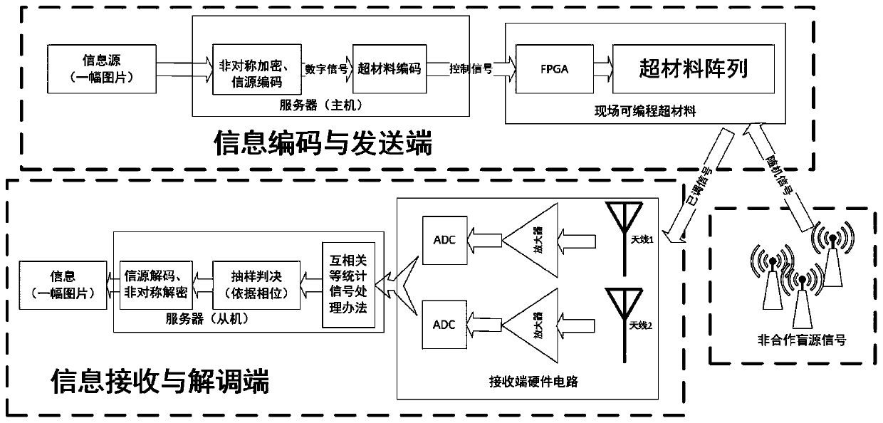
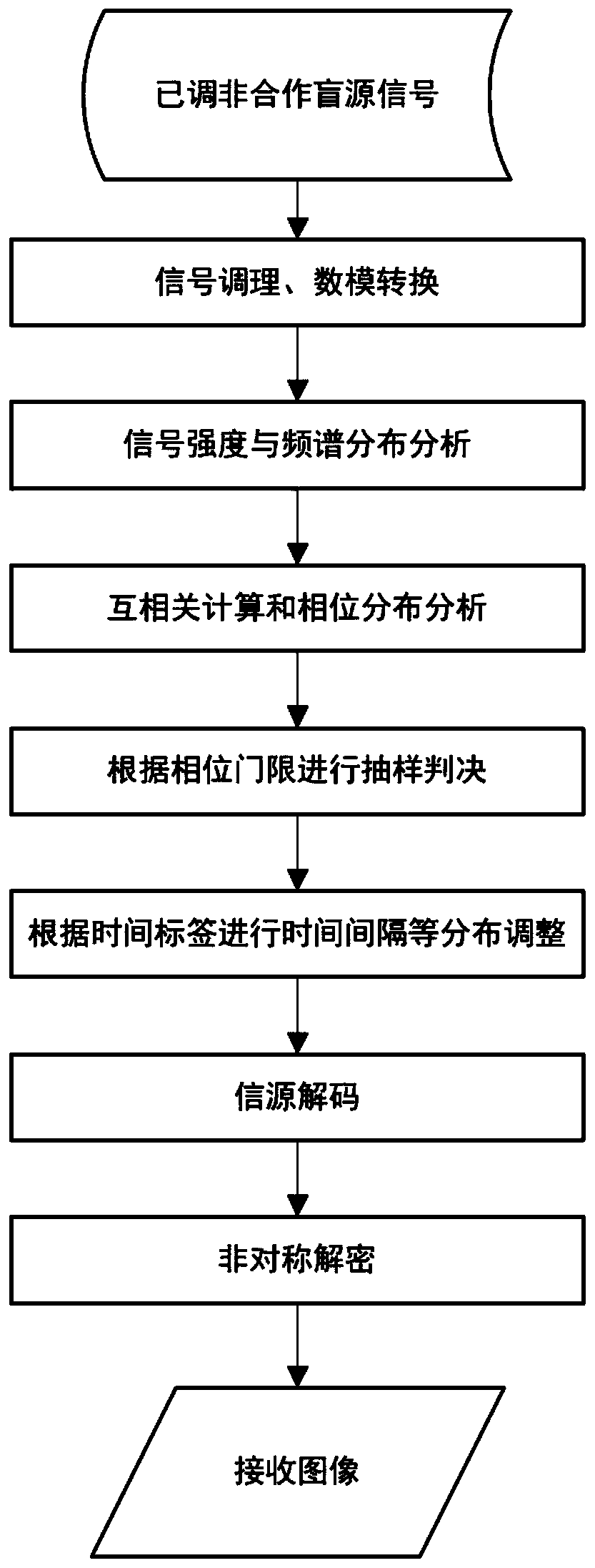
[0051] In this embodiment, the block diagram of the non-cooperative blind source latent communication system based on WI-FI signals is as follows figure 1 shown. The demodulation process of non-cooperative blind source latent communication system based on WI-FI signal is as follows: figure 2 shown. Among them, the information encoding of the non-cooperative blind source latent communication system based on WI-FI signals and the information sent by the sender are as follows: figure 2 As shown on the far left, the information receiver finally decodes the information as follows figure 2 shown in the middle part.

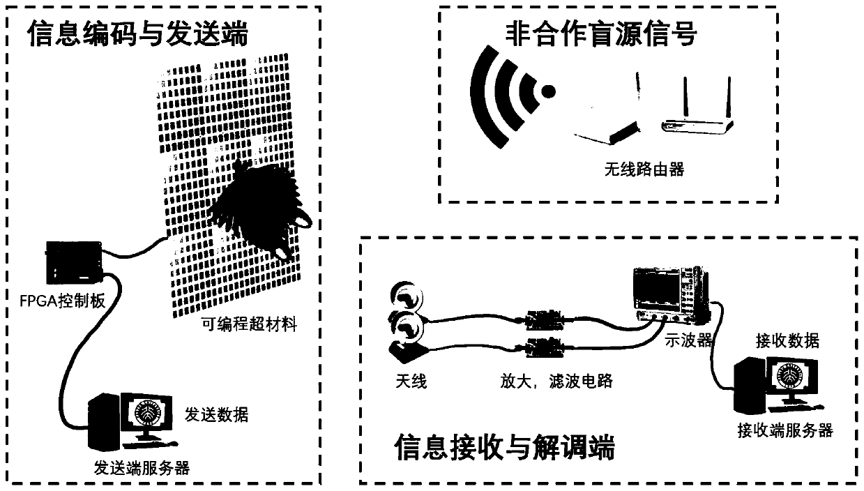
[0052] In this example, the actual devices used in the non-cooperative blind source latent communication system based on WI-FI signals are as follows: image 3 shown.

[0053] Such as image 3 The non-cooperative blind source latent communication system based on WI-FI signals in this example includes the following three components:

[0054] (1) Information codin...


PUM


Abstract

The invention discloses a latent communication system and method based on a non-cooperative blind source. The latent communication system comprises an information coding and transmitting end, an information receiving and demodulating end and a non-cooperative blind source signal, a non-cooperative blind source is used as a communication carrier wave, double antennas or multiple antennas are used as receiving ends, received electromagnetic waves are demodulated in a receiver, and therefore hidden transmission and passive transmission communication of information are achieved. By adopting the technical scheme of the invention, a signal emission source is not needed, the carrier emission power is saved, and new spectrum resources are not occupied; the circuit structure is simplified, and thehardware cost is reduced; concealed communication is guaranteed in the physical level, and indoor directional fixed-point communication can be achieved. Information can be sent to a sensor at a specific position in the Internet of Things, energy is provided for the radio frequency identification tag, and the wireless communication quality is improved.

Description

technical field [0001] The present invention relates to the technical field of covert, passive, passive and latent communication, in particular to a latent communication system and method based on non-cooperative blind source signals. The ubiquitous Wi-Fi, Bluetooth, GPS and other electromagnetic signals are passive communication methods with carrier waves. Background technique [0002] At present, in the field of wireless communication, the modulation and demodulation method used in the existing system needs to modulate the baseband signal onto the carrier. However, in order to increase the transmission rate and reduce the bit error rate, realize normal communication effect and improve communication quality, it is necessary to consider improving the signal-to-noise ratio of the system. There are currently three mainstream ways to improve the signal-to-noise ratio, increasing the carrier power and reducing the noise figure of the receiver, or using special modulation method...

Claims


Application Information

Patent Timeline
Patent Type & Authority Applications(China)
IPC IPC(8): H04K1/02H04W12/02
CPCH04K1/02H04W12/02H04W12/03Y02D30/70
Inventor 赵晗汀魏梦麟双雅李昊洋李廉林
Owner PEKING UNIV
Why Eureka
Try Eureka