Zipper tooth manufacturing device and method and tooth arranging device

A technology for manufacturing devices and chain teeth, which is applied in the field of zipper manufacturing. It can solve problems such as missing teeth, easy flying out, and affecting the zipper manufacturing process, and achieve the effects of improving production efficiency, avoiding missing teeth, and increasing the height distance

Active Publication Date: 2019-09-03
广东顺德三扬科技股份有限公司
View PDF10 Cites 1 Cited by
  • Summary
  • Abstract
  • Description
  • Claims
  • Application Information

AI Technical Summary

Problems solved by technology

[0002] Metal chain elements are generally set in a Y-shaped structure, which includes an engaging head, extending from the engaging head to the rear and branching into left and right feet. When arranging teeth, place the cloth belt between the feet on both sides. And the foot is pressed on the cloth belt. The traditional chain element manufacturing device includes a sliding seat, a cutter and a punch. The sliding seat is provided with a wire channel for supplying the wire upwards. The sliding seat is in sliding contact. ...

Method used


Image

  • Zipper tooth manufacturing device and method and tooth arranging device
  • Zipper tooth manufacturing device and method and tooth arranging device
  • Zipper tooth manufacturing device and method and tooth arranging device

Examples


Embodiment 1

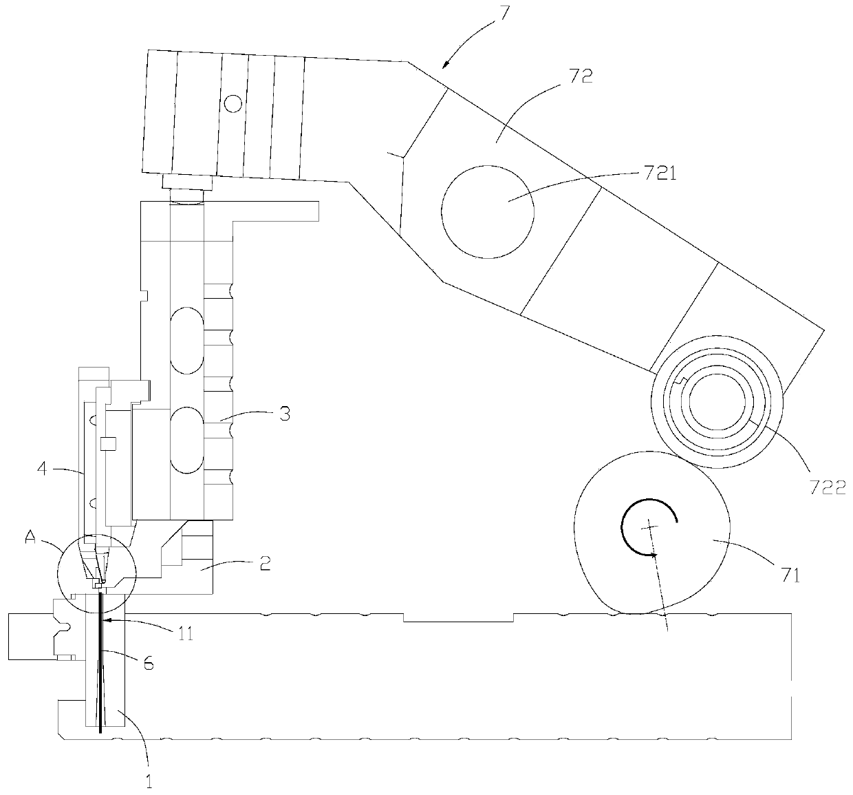
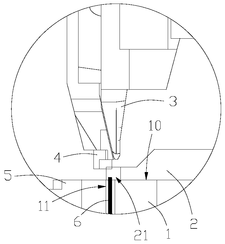
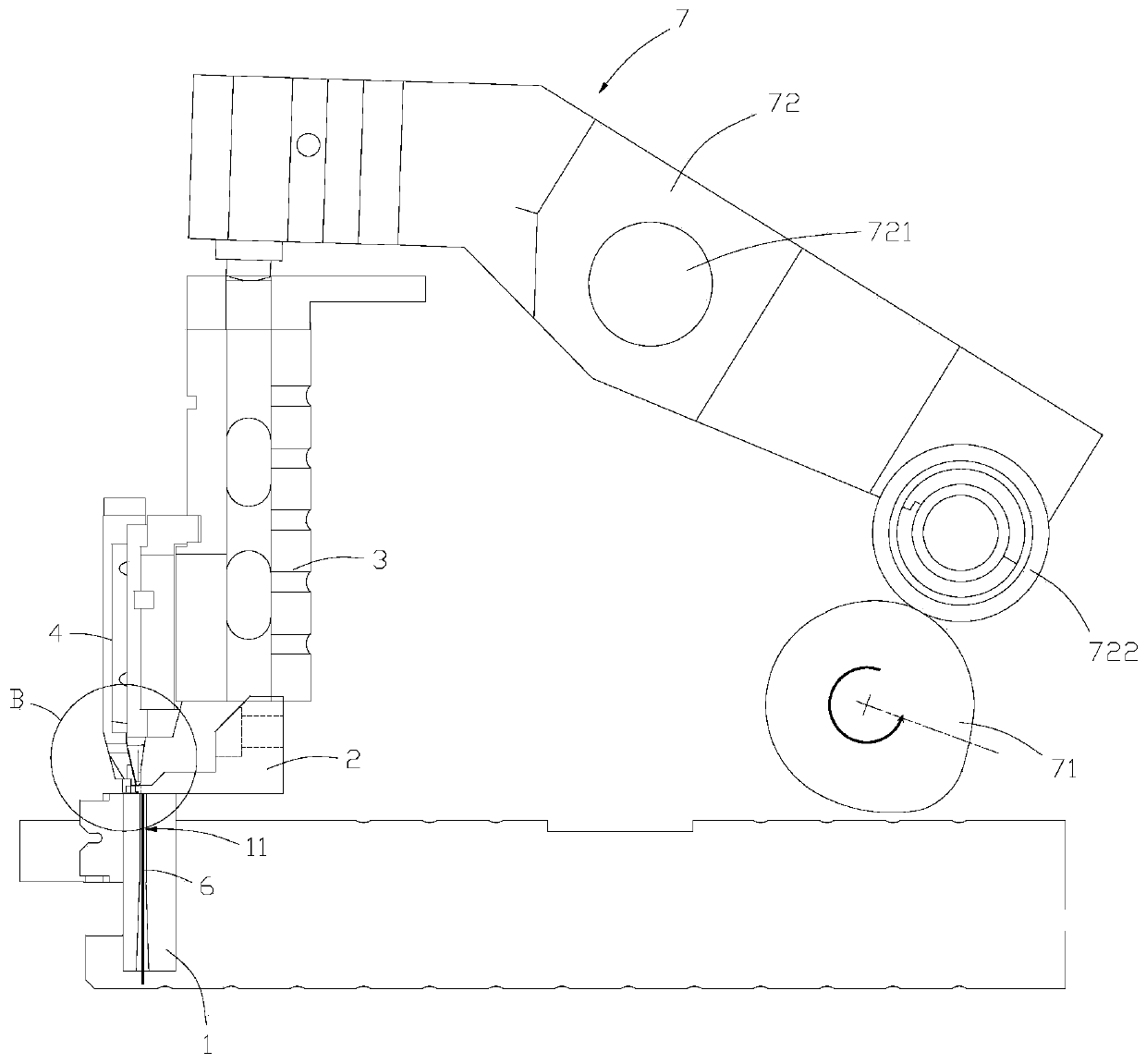
[0039] see Figure 1 to Figure 8 , the present invention provides a fastener element manufacturing device for a zipper, comprising a slide 1 and a cutter 2, a punch 3 and a stripper 4 arranged above the slide 1, and a cutting plane 10 is provided on the upper side of the slide 1 , the interior is provided with a wire channel 11 extending longitudinally from the bottom surface of the slide seat 1 to the cutting plane 10, and the front side is connected with a punching die 5, and the punching die 5 is provided with a forming part 51 located below the cutting plane 10, The wire channel 11 is for the wire 6 to be intermittently delivered to the top of the cutting plane 10 with a preset supply amount every time, and the intermittent delivery of the wire 6 is realized by the feeding mechanism, because the feeding mechanism is not an improvement of the present invention, and the existing Known scheme, so it will not be described in detail; the sliding seat 1 is realized by a driving ...

Embodiment 2

[0047] see Figure 1 to Figure 8 , the present embodiment provides a fastener element manufacturing method of a zipper, which relates to a fastener element manufacturing device, the fastener element manufacturing device includes a slide 1, a punching die 5, a cutter 2, a punch 3 and a stripper 4, the The punching die 5 is arranged on the front side of the slide seat 1, the upper side of the slide seat 1 is provided with a cutting plane 10, and the inside is provided with a wire channel 11 extending longitudinally from the bottom surface of the slide seat 1 to the cutting plane 10, and the punching die 5 is provided with a There is a forming part 51 located below the cutting plane 10. The sliding seat 1 is reciprocated and translated back and forth by the driving mechanism. The cutting knife 2 is in sliding contact with the cutting plane 10. The cutting edge 21 of the cutting knife 2 corresponds to the The wire channel 11, the punch 3 is arranged above the cutting edge 21 in a ...

Embodiment 3

[0052] see Figure 7 , Figure 8 , Figure 10 and Figure 11 , the present embodiment provides a zipper tooth arranging device, which includes the above-mentioned fastener element manufacturing device, a tape supply mechanism and a material clamping mechanism, and the tape supply mechanism includes a feed frame fixed on the front side of the forming part 51 100, the feeding frame 100 is used to load the tape and intermittently convey upwards each time with a preset supply amount, the clamping mechanism includes clamping assemblies 8 arranged on opposite sides above the forming part 51, each side The clamping assembly 8 respectively includes a first clamping arm 81 located on the upper side of the forming part 51 and a second clamping arm 82 located on the upper side of the first clamping arm 81. 100 enters the slot 52 of the forming part 51, when the teeth are arranged, the slide seat 1 moves forward so that the feeding frame 100 is placed in the forming part 51 through the...


PUM


Abstract

The invention belongs to the technical field of zipper manufacturing, and particularly relates to a zipper tooth manufacturing device and method and a tooth arranging device. The zipper tooth manufacturing device comprises a sliding base, a cutting knife, a punching head and a stripping piece, wherein the cutting knife, the punching head and the stripping piece are arranged above the sliding base,a cutting plane is arranged on the upper side of the sliding base, the sliding base is internally provided with a wire rod channel, the front side of the sliding base is connected with a blanking die, a forming part is arranged on the blanking die, the wire rod channel is intermittently conveyed to the upper part of the cutting plane at a preset supply amount for each time, the sliding seat movesback and forth in a reciprocating mode, the cutter is in sliding contact with the cutting plane, a cutting edge is arranged at the front end of the cutting knife, the punching head is arranged abovethe cutting edge in a lifting mode, the stripping piece is arranged on the front side of the punching head in a lifting mode. According to the zipper tooth manufacturing device, when the device is used for cutting, the part of the wire rod protruding cutting plane enters the cutting edge along with the backward movement of the sliding seat, the material removing part is descended to the front sideof the wire rod in the cutting edge, the wire rod in the cutting edge is at least partially shielded, the wire rod is prevented from being thrown out instantly, the phenomenon that the wire is missing during subsequent tooth removal is avoided, the production efficiency is effectively improved, and the reworking rate is reduced.

Description

technical field [0001] The invention belongs to the technical field of zipper manufacturing, in particular to a zipper fastener element manufacturing device and method and a tooth arrangement device. Background technique [0002] Metal chain elements are generally set in a Y-shaped structure, which includes an engaging head, extending from the engaging head to the rear and branching into left and right feet. When arranging teeth, place the cloth belt between the feet on both sides. And the foot is pressed on the cloth belt. The traditional chain element manufacturing device includes a sliding seat, a cutter and a punch. The sliding seat is provided with a wire channel for supplying the wire upwards. The sliding seat is in sliding contact. There is a punching die on the front side of the sliding seat. Slice, and push the slice to the punching die as the slider continues to move backward, and then punch out the engaging convex part on the slice through the punch to form the c...

Claims


Application Information

Patent Timeline
IPC IPC(8): B21F11/00B21D22/04B21D53/52A44B19/44
CPCA44B19/44B21D22/04B21D53/52B21F11/00
Inventor 杨志舜汪怀群关善福
Owner 广东顺德三扬科技股份有限公司
Why Eureka
Try Eureka