

Blind hole workpiece dismounting device
A blind hole and workpiece technology, which is applied in the field of blind hole workpiece disassembly and assembly devices, achieves the effects of non-destructive disassembly, convenient and fast disassembly, and reduced labor intensity
- Summary
- Abstract
- Description
- Claims
- Application Information
AI Technical Summary
Problems solved by technology
Method used
Image

Examples
Embodiment 1
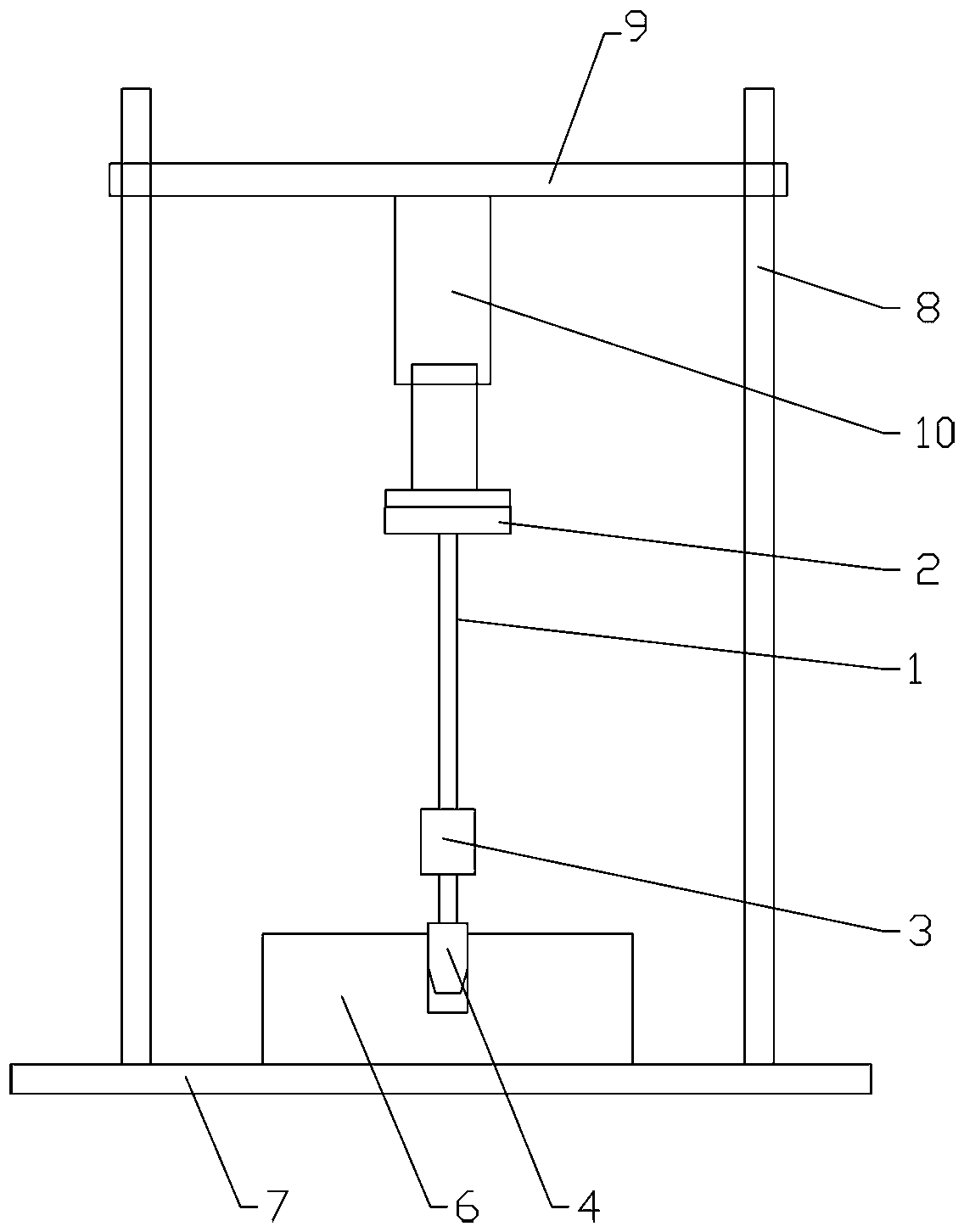
[0018] The main structure includes a base 7 and a dowel bar 1. The bottom of the dowel bar 1 is provided with a self-centering conversion chuck 3, and the pressure rod head 4 is installed on the self-centering conversion chuck 3. The top of the dowel bar 1 is a press-fit top. Disk 2. The pressing rod head 4 squeezes the shaft type workpiece in the blind hole on the workpiece 6 .
[0019] The upper side of the base 7 is a horizontal plane, and two columns 8 are fixed on the base, and the two columns 8 are vertical and parallel to each other. The tops of the two columns 8 are provided with fixed crossbeams, and the crossbeams are arranged horizontally. A hydraulic cylinder 10 is arranged in the middle of the beam 9, and the piston of the hydraulic cylinder 10 faces downward.
[0020] The piston of the hydraulic cylinder 10 contacts the press-mounted top plate 2 to press down the dowel 1, the workpiece 6 with a blind hole is placed on the base 7, and the pressure rod head 4 squ...
Embodiment 2
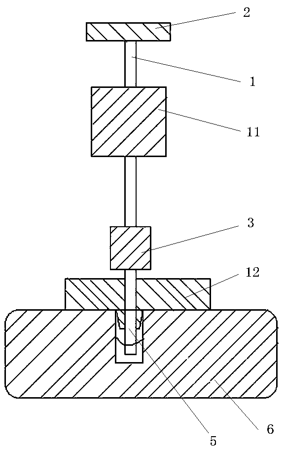
[0023] The main structure includes a dowel bar 1, an impact hammer 11 is set on the dowel bar 1, the top of the dowel bar 1 is a press-fit top plate 2, and the bottom of the dowel bar 1 is provided with a self-centering conversion chuck 3, which is self-centering. A tie rod head 5 is installed on the conversion chuck 3 .
[0024] The tie rod head 5 is provided with a shaft positioning seat 12, specifically the lower end of the draw bar head 5 passes through the shaft positioning seat 12, the shaft positioning seat 12 is arranged at the blind hole position of the workpiece 6, and the shaft positioning seat 12 The through hole of the tie rod head 5 is concentric with the inner part of the blind hole.
[0025] The tie rod head and the blind hole internal part are connected by thread. Specifically, a screw hole is opened in the center of the blind hole internal part. The 5 ends of the tie rod head are fixed with the screw holes on the part. Pull up after fixing.
[0026] Hold th...
Embodiment 3
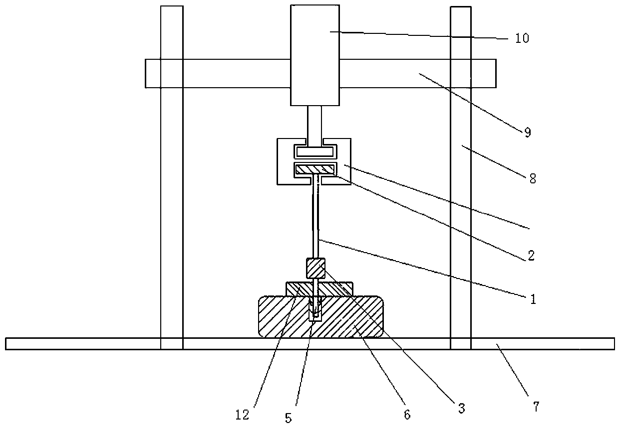
[0029] The main structure includes a dowel bar 1 and a base 7, the top of the dowel bar 1 is a press-fit top plate 2, the bottom of the dowel bar 1 is provided with a self-centering conversion chuck 3, and a tie rod head is installed on the self-centering conversion chuck 3 5.
[0030] The upper side of the base 7 is a horizontal plane, and two columns 8 are fixed on the base, and the two columns 8 are vertical and parallel to each other. The tops of the two columns 8 are provided with fixed crossbeams, and the crossbeams are arranged horizontally. A hydraulic cylinder 10 is arranged in the middle of the beam 9, and the piston of the hydraulic cylinder 10 faces downward.
[0031] The pull-press conversion joint 13 has T-shaped grooves on the upper and lower sides of the pull-pressure conversion joint 13, and the top of the dowel 1 is pressed into the top plate 2 and the piston end of the hydraulic cylinder 10 is embedded in the T-shaped groove. Inside.
[0032] The tie rod ...
PUM
 Abstract
Description
Claims
Application Information