Concrete centrifuge

A centrifuge and concrete technology, applied in the direction of molds, etc., can solve the problems of uneven finished pipe piles and easy jumping

Pending Publication Date: 2019-09-03
盐城市双强管桩有限公司
View PDF0 Cites 3 Cited by
  • Summary
  • Abstract
  • Description
  • Claims
  • Application Information

AI Technical Summary

Problems solved by technology

[0004] Therefore, the technical problem to be solved by the present invention lies in the defects in the prior art that the finished pipe piles are uneven due to the easy jump of the mold body.

Method used


Image

  • Concrete centrifuge
  • Concrete centrifuge

Examples


Embodiment 1

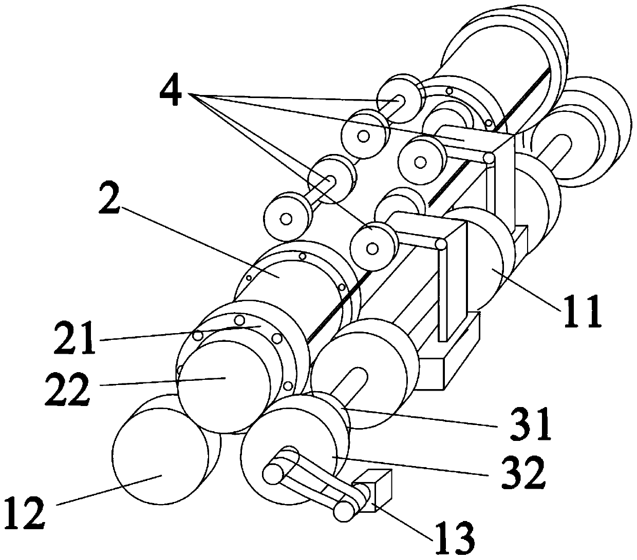
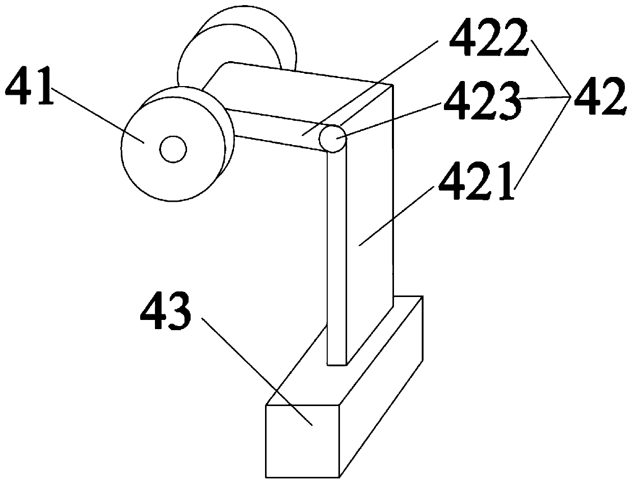
[0037] This embodiment provides a concrete centrifuge, such as Figure 1 to Figure 2 As shown, it includes a base frame and a driving mechanism and a shock absorbing mechanism 4 arranged on the base frame. Wherein, the driving mechanism has a driving unit 13 and a supporting unit, the driving unit 13 drives the supporting unit to rotate, and the supporting unit is rotatably supported on the rotating outer peripheral surface of the mold 2; Rotate the damping unit 41 on the outer peripheral surface, and the damping unit 41 applies a force to the mold 2 to limit its departure from the initial rotation position; the supporting unit and the damping mechanism 4 are along both sides of the outer surface of the mold 2; the damping mechanism 4 is set between any two supporting units. The force exerted by the damping mechanism 4 on the mold 2 partially offsets the force exerted by the supporting unit on the mold 2 . Such as figure 1 As shown, two groups of shock absorbing units 4 are...

Embodiment 2

[0046] This embodiment provides a concrete centrifuge, which differs from the concrete centrifuge provided in Embodiment 1 in that the structure of the driving mechanism is different:

[0047] In this embodiment 2, when the main body wheel 31 is not considered to cause the wheel body structure to burst due to the different pressure bearing capacity, the supporting unit of the driving mechanism may not be provided with the explosion-proof wheel 32, and the mold 2 can be adjusted by setting a plurality of main body wheels 31. load bearing.

Embodiment 3

[0049] This embodiment provides a concrete centrifuge, which differs from the concrete centrifuge provided in Embodiment 1 or Embodiment 2 in that multiple driving units 13 can be provided, and the active support of the supporting unit The number of wheels 11 and driven supporting wheels 12 changes:

[0050] For example, two driving units 13 are provided, and the two driving units 13 are respectively arranged at both ends of the mold 2 in the axial direction. 2. At both ends of the axial direction, multiple groups of driven supporting rollers 12 can be set on the left or right side of the bottom of the mold 2, as long as they avoid the driving supporting rollers 11. When the driving supporting rollers 11 drive the mold 2 to rotate, from The movable support roller 12 can rotate under the drive of the mold 2 to get final product.


PUM


Abstract

The invention discloses a concrete centrifuge. The concrete centrifuge comprises a base frame, a drive mechanism arranged on the base frame, and damping mechanisms. The drive mechanism is provided with drive units and supporting units. The drive units drive the supporting units to rotate, and the supporting units are rotationally supported on the rotary peripheral surface of a die. The damping mechanisms comprise damping units rotationally abutting against the rotary peripheral surface of the die, and the damping units apply acting force for limiting the die from being separated from an initial rotary position to the die. The supporting units and the damping mechanisms are arranged along the two sides of the outer surface of the die. One damping mechanism is arranged between any two supporting units. According to the concrete centrifuge of the structure, when the die is driven by the drive mechanism to rotate, if the die has a jump trend, the damping units apply the acting force for limiting the die from being separated from the initial rotary position to the die, in other words, the damping units abut against the peripheral surface of the wall face die to prevent jump generated when the die rotates, and then the purpose that finished pipe piles are uniform is guaranteed.

Description

technical field [0001] The invention relates to the technical field of construction processing, in particular to a concrete centrifuge. Background technique [0002] Pipe piles are widely used in the production of concrete well pipes, construction pipe piles, utility poles and other production industries. 1. The six major links of ordinary steaming and autoclaving. Among them, the main equipment of the centrifugal forming process is composed of a centrifuge and a mold, and a mold wheel is installed on the mold. The centrifuge is composed of a frame, a supporting wheel and an electric motor. Place the mold containing the concrete mixture on the supporting wheels at both ends of the centrifuge, and it is driven by the motor to rotate. Through the centrifugal force generated by the rotation, the water in the concrete is squeezed out to form a hard and dense concrete. status. [0003] However, since the mold is usually relatively long, the mold body tends to bounce up and do...

Claims


Application Information

Patent Timeline
IPC IPC(8): B28B21/80
CPCB28B21/80
Inventor 凌德祥
Owner 盐城市双强管桩有限公司
Why Eureka
Try Eureka