Supercharge Your Innovation With Domain-Expert AI Agents!

Injection molding waste gas extraction equipment

An equipment and waste gas technology, applied in the field of injection molding waste gas extraction equipment, can solve the problems of poor pipeline gas path, affecting gas circulation, endangering the health of workers, etc., to improve waste gas extraction efficiency, improve extraction efficiency and reduce waste gas escape Effect

Inactive Publication Date: 2019-09-03
芜湖德鑫塑模有限公司
View PDF4 Cites 0 Cited by
  • Summary
  • Abstract
  • Description
  • Claims
  • Application Information

AI Technical Summary

Problems solved by technology

[0003] However, the waste gas generated by the injection molding equipment will be dispersed, and it will inevitably cause a lot of waste gas to escape, pollute the environment and endanger the health of workers
[0004] Moreover, at present, the production workshops of common plastic manufacturers are not dust-free workshops, and the exhaust gas extraction will also remove a large amount of dust and particulate matter, while the special injection molding exhaust gas treatment equipment is not capable of processing dust and particulate matter. Therefore, it is often equipped with A dust adsorption device or filter device; most of the dust adsorption or filter devices have defects, which will affect the gas circulation, such as the filter element or filter screen working for a long time, a large amount of dust will accumulate, and the gas path of the pipeline will be blocked or even blocked. The filter element or filter screen needs to be dismantled and cleaned frequently or replaced with new ones, which is very troublesome and increases the cost

Method used


Image

  • Injection molding waste gas extraction equipment
  • Injection molding waste gas extraction equipment
  • Injection molding waste gas extraction equipment

Examples


Embodiment Construction

[0024] In order to make the technical means, creative features, goals and effects achieved by the present invention easy to understand, the present invention will be further described below in conjunction with specific embodiments.

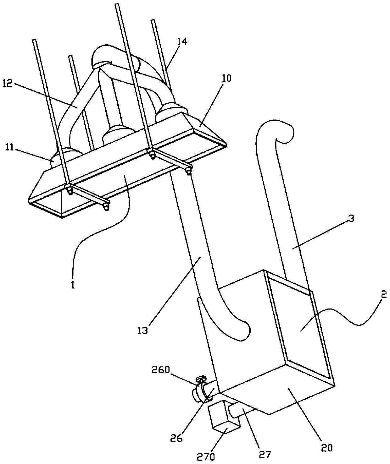
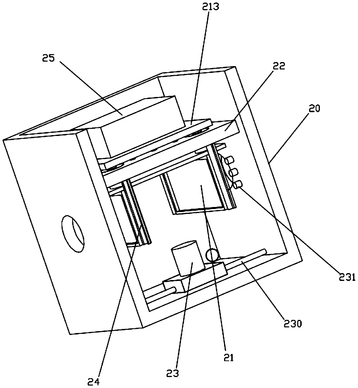
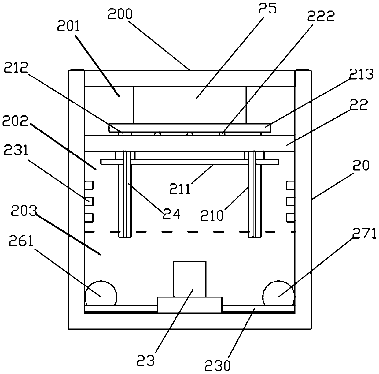
[0025] Such as Figure 1 to Figure 8 As shown, an injection molding exhaust gas extraction equipment includes an air extraction structure 1, a dust removal mechanism 2, and an air outlet pipeline 3. The air extraction structure 1, dust removal mechanism 2, and air outlet pipeline 3 are connected in sequence; the air outlet pipeline 3 is connected to the exhaust gas treatment equipment.

[0026] Described air extraction structure 1 comprises trumpet air extraction port 10, blower fan 11, air extraction branch pipe 12, air extraction main pipe 13 and hanger 14, and described air extraction branch pipe 12 is provided with several groups, and the upper and lower ends of air extraction branch pipe 12 are connected with the air extraction branch pipe res...


PUM


Abstract

The invention discloses injection molding waste gas extraction equipment, and relates to the field of injection molding waste gas treatment. The injection molding waste gas extraction equipment comprises an air suction structure, a dust removal mechanism and an air outlet pipeline, wherein the air suction structure, the dust removal mechanism and the air outlet pipeline are sequentially in communication. By arranging a horn air suction port, the opening diameter of the air suction port is increased, and by arranging multiple sets of draught fans to be matched with different branch pipelines, the waste gas extraction efficiency is greatly improved; meanwhile, the dust removal mechanism is also arranged so that dust particles can be removed in the process that the waste gas is led to processing equipment; a vibration motor and a scattering nozzle are arranged so that the dust on a filter screen can be frequently shaken and cleaned, then the filter screen does not need to be replaced frequently, the labor is saved and the cost is reduced; and the waste gas extraction efficiency is improved, waste gas escaping is reduced, the dust removal can be realized, the filter screen can be automatically cleaned, and the labor is saved.

Description

technical field [0001] The invention relates to the field of injection molding waste gas treatment, in particular to injection molding waste gas extraction equipment. Background technique [0002] At present, plastic production factories are equipped with injection molding waste gas extraction equipment and waste gas treatment equipment. Among them, the injection molding waste gas extraction equipment in most factories is relatively simple, basically a fan with a suction port, and the suction port faces the injection molding. The place where the exhaust gas of the equipment is generated, so that most of the exhaust gas generated when the injection molding equipment is working will be sucked away; [0003] However, the exhaust gas generated by the injection molding equipment will be scattered, and it is inevitable that a lot of exhaust gas will escape when the air is drawn from one exhaust port, polluting the environment and endangering the health of workers. [0004] Moreov...

Claims


Application Information

Patent Timeline
Patent Type & Authority Applications(China)
IPC IPC(8): B29C45/17B08B15/04B01D46/12B01D46/00
CPCB29C45/17B08B15/04B01D46/12B01D46/66B01D46/76
Inventor 仇多金贾治国丁诗强王敏李建张祖传
Owner 芜湖德鑫塑模有限公司
Features
  • R&D
  • Intellectual Property
  • Life Sciences
  • Materials
  • Tech Scout
  • Unparalleled Data Quality
  • Higher Quality Content
  • 60% Fewer Hallucinations
Learn More