Movable speed measuring instrument

A speedometer, mobile technology, applied in the direction of supporting machines, mechanical equipment, machine/stands, etc., can solve problems such as the influence of wheel stability, and achieve the effect of ensuring stability and facilitating movement

Active Publication Date: 2019-09-03
ZHONGMENG KECHUANG SHENZHEN TECH DEV
View PDF5 Cites 5 Cited by
  • Summary
  • Abstract
  • Description
  • Claims
  • Application Information

AI Technical Summary

Problems solved by technology

[0004] The purpose of the present invention is to solve the problem in the prior art that the support needs to be stabilized on the ground when performing speed measurement. At this time, its stability is affected due to the existence of wheels, and a mobile speed measuring instrument is proposed.

Method used


Image

  • Movable speed measuring instrument
  • Movable speed measuring instrument
  • Movable speed measuring instrument

Examples


Embodiment 1

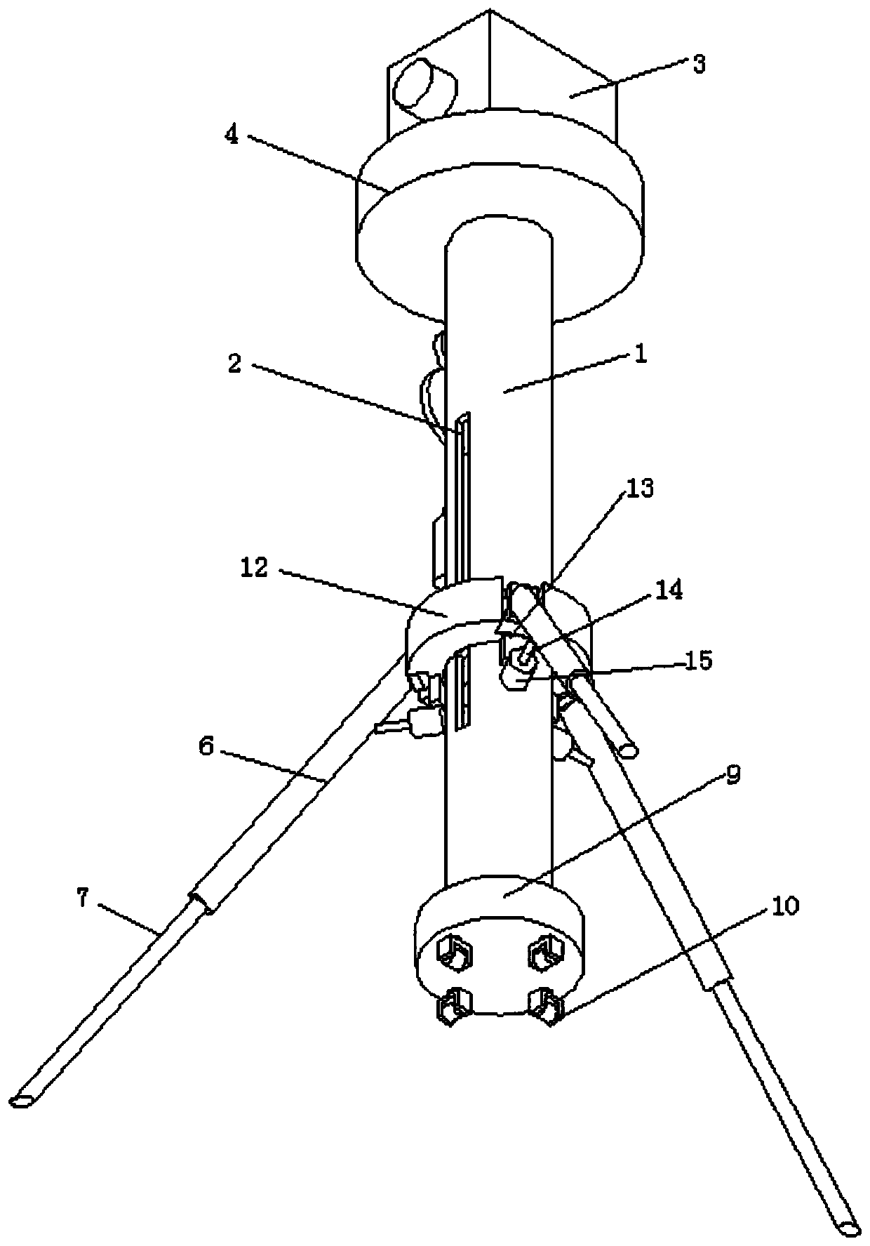
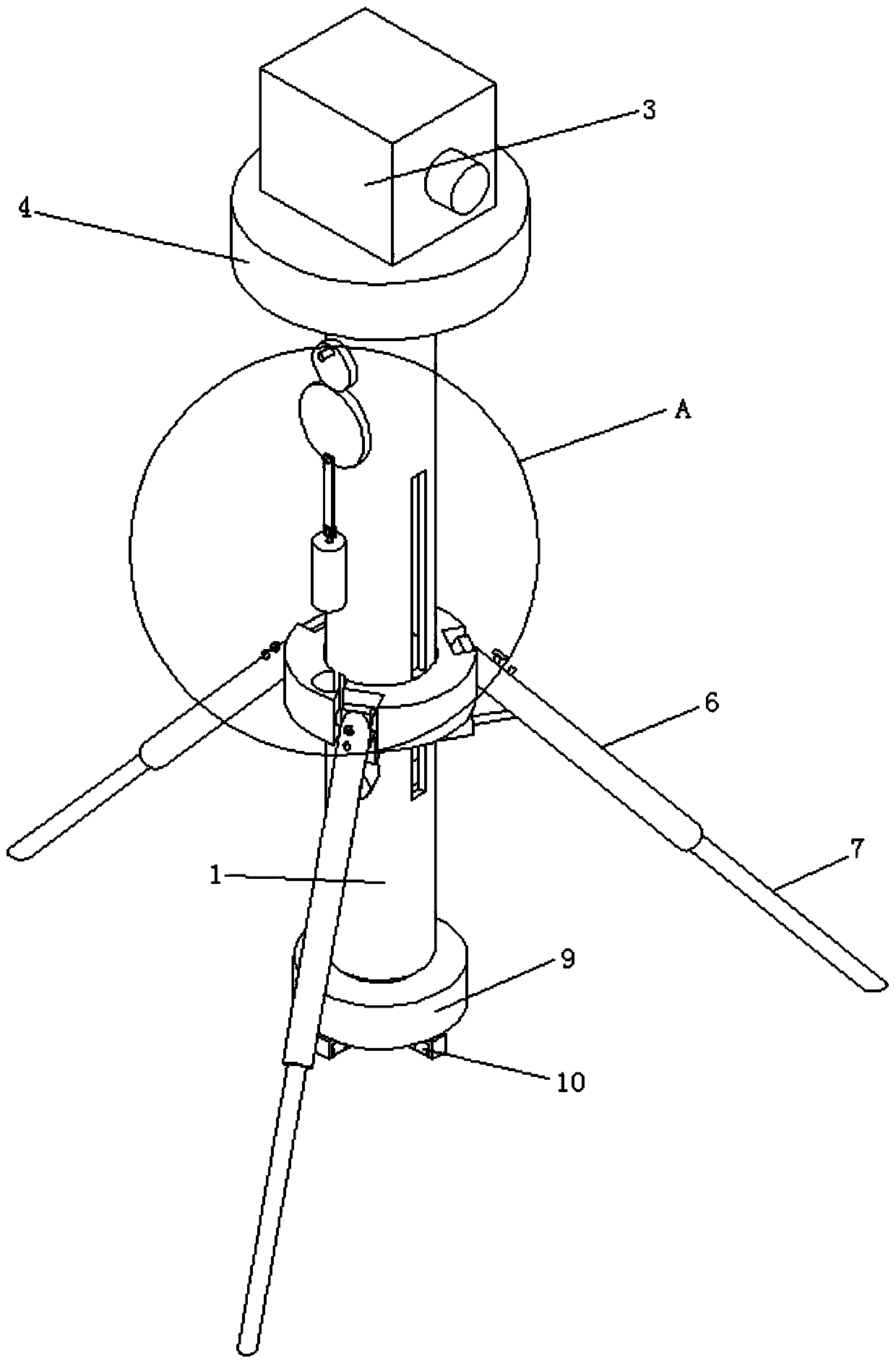
[0031] refer to Figure 1-9 , a mobile speedometer, comprising a radar speedometer 3 and a support cylinder 1, the support cylinder 1 supports the radar speedometer 3 through a support plate 4, a base 9 is provided for sliding on the bottom side of the support cylinder 1, and a universal joint is connected to the bottom side of the base 9 The wheel 10 and the base 9 are slidably connected to the bottom side of the support cylinder 1 through the insertion rod 8. The support cylinder 1 is slidably connected with a sliding sleeve 12, and the sliding sleeve 12 is connected with a support leg 6; when the speedometer needs to be moved, the sliding sleeve 12 The upward movement drives the supporting legs 6 to move upwards, leaving the ground, and the insertion rod 8 on the bottom side of the supporting cylinder 1 is pulled out downwards, so that the base 9 moves downwards, and the universal wheels 10 touch the ground, so that it is easy to move and realize different road sections. Fo...

Embodiment 2

[0034] refer to Figure 1-9 , a mobile speedometer, comprising a radar speedometer 3 and a support cylinder 1, the support cylinder 1 supports the radar speedometer 3 through a support plate 4, a base 9 is provided for sliding on the bottom side of the support cylinder 1, and a universal joint is connected to the bottom side of the base 9 The wheel 10 and the base 9 are slidably connected to the bottom side of the support tube 1 through the insertion rod 8. The support tube 1 is slidably connected with a sliding sleeve 12, and the sliding sleeve 12 is connected with a support leg 6; when the speedometer needs to be moved, the sliding sleeve 12 The upward movement drives the support legs 6 to move upwards, leaving the ground, and the insertion rod 8 on the bottom side of the support cylinder 1 is pulled out downwards, so that the base 9 moves downwards, and the universal wheels 10 touch the ground, so that it is easy to move and realize different road sections. For detection, b...

Embodiment 3

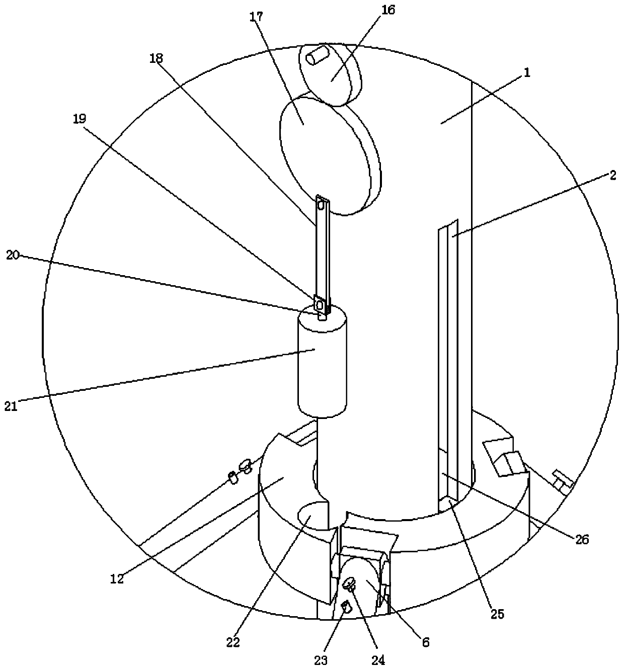
[0039] refer to Figure 1-9 , a mobile velocimeter, basically the same as Embodiment 2, furthermore, the lifting plate 26 and the sliding sleeve 12 are fixedly connected through the connecting block 25, and the supporting cylinder 1 is provided with a sliding port 2 matching the connecting block 25, The lifting plate 26 and the sliding sleeve 12 can be connected stably through the connecting block 25, and the sliding opening 2 provided by the support cylinder 1 ensures that the lifting plate 26 and the sliding sleeve 12 can slide up and down while being fixedly connected on the support cylinder 1;

[0040] A piston 41 is slidably connected in the pneumatic cylinder 15, and the piston 41 is fixedly connected with the pneumatic rod 14, and the air release valve 40 is connected to the pneumatic cylinder 15; by inflating the pneumatic cylinder 15, the piston 41 is pushed to move, thereby realizing the The movement of the pneumatic rod 14 facilitates the expansion of the supporting...


PUM


Abstract

The invention discloses a movable speed measuring instrument, and belongs to the field of traffic tools. The movable speed measuring instrument comprises a radar speed measuring instrument body and asupporting cylinder, wherein the supporting cylinder supports the radar speed measuring instrument body through a supporting plate, a base is arranged on the bottom side of the supporting cylinder ina sliding mode, the bottom side of the base is connected with universal wheels, the base is slidably connected to the bottom side of the supporting cylinder through an inserting rod, a sliding sleeveis slidably connected to the supporting cylinder, and supporting legs are connected to the sliding sleeve. The instrument have the advantages that different road segments can be detected, but the instrument needs to be placed on the roadside for detection, the inserting rod moves upwards to put the base and the universal wheels away, meanwhile, the sliding sleeve is moved downwards, the sliding sleeve drives the supporting legs to be moved downwards, so that the supporting legs support the radar speed measuring instrument body for speed measuring, at the moment, the universal wheels are separated from the ground, the supporting legs are used for supporting, so that the stability is ensured, moving is facilitated when moving is required, and a support is required to be fixed on the ground when speed measuring is carried out, so that the stability of the instrument is ensured.

Description

technical field [0001] The invention relates to the technical field of vehicles, in particular to a mobile speedometer. Background technique [0002] In recent years, with the continuous growth of the number of urban motor vehicles, while bringing many conveniences, there are also some problems; vehicle violations emerge in endlessly, and traffic accidents occur frequently, which have caused certain difficulties to urban traffic management. Today, science and technology require police power, and technology requires efficiency." It is very necessary to make full use of high-tech means to develop and develop products that can correct and curb traffic violations, effectively realize traffic management, and improve transportation efficiency. [0003] The functions of mobile speedometers are relatively diversified, and the application range of mobile speedometers is relatively wider, including some large factories such as factories, mines, airports, and docks. There are also mobi...

Claims


Application Information

Patent Timeline
Patent Type & Authority Applications(China)
IPC IPC(8): F16M11/42
CPCF16M11/42F16M2200/08
Inventor 不公告发明人
Owner ZHONGMENG KECHUANG SHENZHEN TECH DEV
Why Eureka
Try Eureka