Low-voltage line loss segmented acquisition measurer
A measurer and low-voltage line technology, which is applied in the field of low-voltage line loss segmental acquisition measurer, can solve the problems of high construction cost, hidden dangers of staff safety, and great difficulty in acquisition and measurement of staff, so as to achieve convenient operation and reduce safety. Hidden danger, fast and convenient height adjustment effect
- Summary
- Abstract
- Description
- Claims
- Application Information
AI Technical Summary
Problems solved by technology
Method used
Image
Examples
Embodiment 1
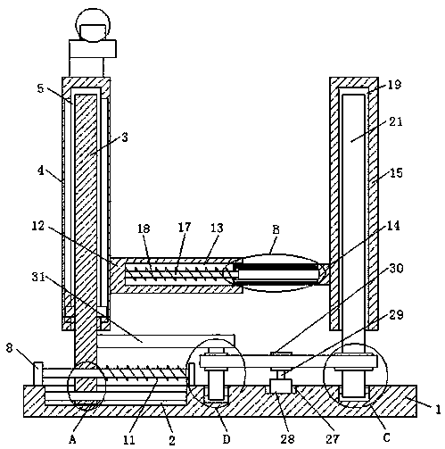
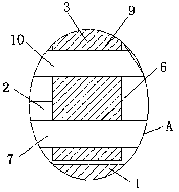
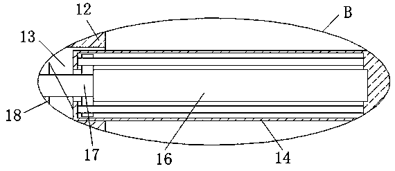
[0027] refer to Figure 1-3 , a low-voltage line loss segmental acquisition measuring device, including a mounting base 1, a movable groove 2 is provided on the top of the mounting base 1, a movable column 3 is slidably installed in the movable groove 2, a sliding plate 4 is arranged on the top of the mounting base 1, and the sliding plate The bottom of 4 is provided with a sliding groove 5, and the top of the movable column 3 extends into the sliding groove 5 and is slidably connected with the sliding groove 5, and a limiting hole 6 is provided on the movable column 3, and a limiting rod 7 is slidably installed in the limiting hole 6. , and the two ends of the limit rod 7 are respectively fixedly connected with the inner wall of one side of the corresponding movable groove 2, and the top of the mounting seat 1 is fixedly equipped with two limit blocks 8, and the movable column 3 is provided with a limit hole 6 The embedding hole 9 on the top, the embedding rod 10 is slidably ...
Embodiment 2
[0036] refer to Figure 1-3 , a low-voltage line loss segmental acquisition measuring device, including a mounting base 1, a movable groove 2 is provided on the top of the mounting base 1, a movable column 3 is slidably installed in the movable groove 2, a sliding plate 4 is arranged on the top of the mounting base 1, and the sliding plate The bottom of 4 is provided with a sliding groove 5, and the top of the movable column 3 extends into the sliding groove 5 and is slidably connected with the sliding groove 5, and a limiting hole 6 is provided on the movable column 3, and a limiting rod 7 is slidably installed in the limiting hole 6. , and the two ends of the limit rod 7 are fixedly connected with the inner wall of one side of the corresponding movable groove 2 respectively, and the top of the mounting base 1 is fixedly connected with two limit blocks 8 by bolts, and the movable column 3 is provided with a position limit block 8. In the embedding hole 9 above the hole 6, an ...
PUM
 Abstract
Description
Claims
Application Information
 - R&D
- Intellectual Property
- Life Sciences
- Materials
- Tech Scout
- Unparalleled Data Quality
- Higher Quality Content
- 60% Fewer Hallucinations
Browse by: Latest US Patents, China's latest patents, Technical Efficacy Thesaurus, Application Domain, Technology Topic, Popular Technical Reports.
© 2025 PatSnap. All rights reserved.Legal|Privacy policy|Modern Slavery Act Transparency Statement|Sitemap|About US| Contact US: help@patsnap.com


