An array antenna main lobe interference suppression method and system

A technology of array antenna and main lobe interference, which is applied in the field of array antenna main lobe interference suppression method and system, can solve the problems of effect degradation and achieve good robustness, high output signal-to-interference-noise ratio SINR, and high-precision effects

Active Publication Date: 2021-02-12
ROCKET FORCE UNIV OF ENG
View PDF6 Cites 0 Cited by
  • Summary
  • Abstract
  • Description
  • Claims
  • Application Information

AI Technical Summary

Problems solved by technology

However, the effect of this method is reduced in the environment of multiple main lobe interference

Method used


Image

  • An array antenna main lobe interference suppression method and system
  • An array antenna main lobe interference suppression method and system
  • An array antenna main lobe interference suppression method and system

Examples


Embodiment 1

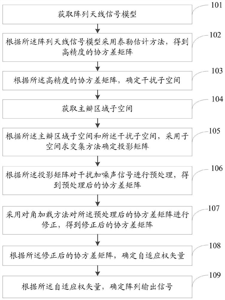
[0067] figure 1 It is a flow chart of the method for suppressing the main lobe interference of the array antenna of the present invention. Such as figure 1 As shown, an array antenna main lobe interference suppression method includes:

[0068] Step 101: Obtain the array antenna signal model;

[0069] Step 102: Using the Taylor estimation method according to the array antenna signal model to obtain a high-precision covariance matrix, specifically including:

[0070] According to the array antenna signal model, the Taylor estimation method is used to obtain a high-precision covariance matrix

[0071] in, p i is the power of the i-th interference, are the estimated noise power, I is the identity matrix, A=[a(θ 1 ),…,a(θ p+q )], a(θ i ) is the steering vector corresponding to the i-th interference, θ i is the incoming wave direction of the i-th interference.

[0072] Step 103: Determine the interference subspace according to the high-precision covariance matrix, spe...

Embodiment 2

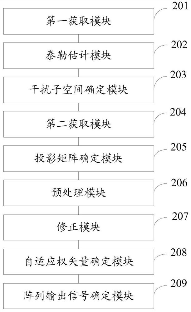
[0095] figure 2 It is a structural diagram of the array antenna main lobe interference suppression system of the present invention. Such as figure 2As shown, an array antenna main lobe interference suppression system includes:

[0096] The first acquiring module 201 is configured to acquire an array antenna signal model;

[0097] A Taylor estimation module 202, configured to obtain a high-precision covariance matrix by using a Taylor estimation method according to the array antenna signal model;

[0098] An interference subspace determination module 203, configured to determine the interference subspace according to the high-precision covariance matrix;

[0099] The second acquiring module 204 is configured to acquire the subspace of the main lobe region;

[0100] The projection matrix determination module 205 is configured to determine the projection matrix by using the subspace intersection method according to the main lobe area subspace and the interference subspace; ...

Embodiment 3

[0109] A method for suppressing main lobe interference of an array antenna, comprising:

[0110] Step 301: Obtain an array antenna signal model;

[0111] Consider a uniform line array (uniform line array, ULA) composed of M array elements, and the interval between the array elements is half a wavelength. First, the antenna only receives signals and does not transmit signals. The obtained snapshot data only contains interference and noise, but does not contain expected signals, and is used as training data. It is assumed that interference and interference, interference and noise are independent of each other, and that all signals are narrowband far-field signals. Among them, the number of main lobe interference is p, the number of side lobe interference is q, and the incident angle is θ 1 ,…,θ p+q . Then the training data received by the array is:

[0112]

[0113] where a(θ i ) is the steering vector corresponding to the i-th interference, θ i is the incoming wave di...


PUM


Abstract

The invention discloses an array antenna main lobe interference suppression method and system. The method includes: obtaining an array antenna signal model; using a Taylor estimation method according to the array antenna signal model to obtain a high-precision covariance matrix; determining an interference subspace according to the high-precision covariance matrix; obtaining a main lobe area subspace ; According to the main lobe subspace and the interference subspace, the projection matrix is ​​determined by using the subspace intersection method; the interference plus noise signal is preprocessed according to the projection matrix, and the preprocessed covariance matrix is ​​obtained; The diagonal loading method corrects the covariance matrix after the pretreatment to obtain the covariance matrix after correction; according to the covariance matrix after correction, determine the adaptive weight vector; according to the adaptive weight vector, determine Array output signal. The method or system of the present invention can effectively suppress the interference of multiple main lobes, and maintain good robustness under low snapshot conditions.

Description

technical field [0001] The invention relates to the field of main lobe interference, in particular to a method and system for suppressing main lobe interference of an array antenna. Background technique [0002] With the increasingly severe electronic countermeasures, the requirements for radar anti-jamming performance are getting higher and higher. Phased array radar is widely used due to its flexible beam steering performance. Adaptive beam forming (ABF) technology can realize the formation of nulls in unknown interference directions, and better suppress side lobe interference. However, when interference enters the main lobe, the traditional ABF will form a null in the main lobe, resulting in distortion of the pattern and seriously affecting the detection performance of the radar. For example, it will distort the angle measurement curve of the monopulse radar and greatly reduce its angle measurement accuracy. . [0003] In order to solve the above problems, the researche...

Claims


Application Information

Patent Timeline
Patent Type & Authority Patents(China)
IPC IPC(8): G01S7/28G01S7/36
CPCG01S7/2813G01S7/36
Inventor 金伟沈晓卫张峰干贾维敏陈卓伍宗伟袁丁
Owner ROCKET FORCE UNIV OF ENG
Why Eureka
Try Eureka