Joint test system and method based on 2M optical interface protection device

A technology of combined testing and protection devices, applied in transmission monitoring/testing/fault measurement systems, selection devices, selection devices of multiplexing systems, etc., can solve low accuracy, low efficiency and accuracy, and lack of solutions and other issues, to achieve the effect of great practical value, improving efficiency and accuracy

Inactive Publication Date: 2019-09-03
INFORMATION COMM COMPANY STATE GRID SHANDONG ELECTRIC POWER
View PDF4 Cites 1 Cited by
  • Summary
  • Abstract
  • Description
  • Claims
  • Application Information

AI Technical Summary

Problems solved by technology

Because it is necessary to test the compatibility and performance between the 2M optical interface board and the protection equipment of any manufacturer, using the existing test method to continuously replace the protection equipment in the test system, the test efficiency is low, and a single test cannot guarantee the consistency of the test environment sex, low accuracy
[0010] To sum up, in the prior art, there is still a lack of an effective solution to the problem of low efficiency and accuracy of the test method for the compatibility and performance between the 2M optical interface board and the protection equipment of any manufacturer.

Method used


Image

  • Joint test system and method based on 2M optical interface protection device
  • Joint test system and method based on 2M optical interface protection device
  • Joint test system and method based on 2M optical interface protection device

Examples


Embodiment 1

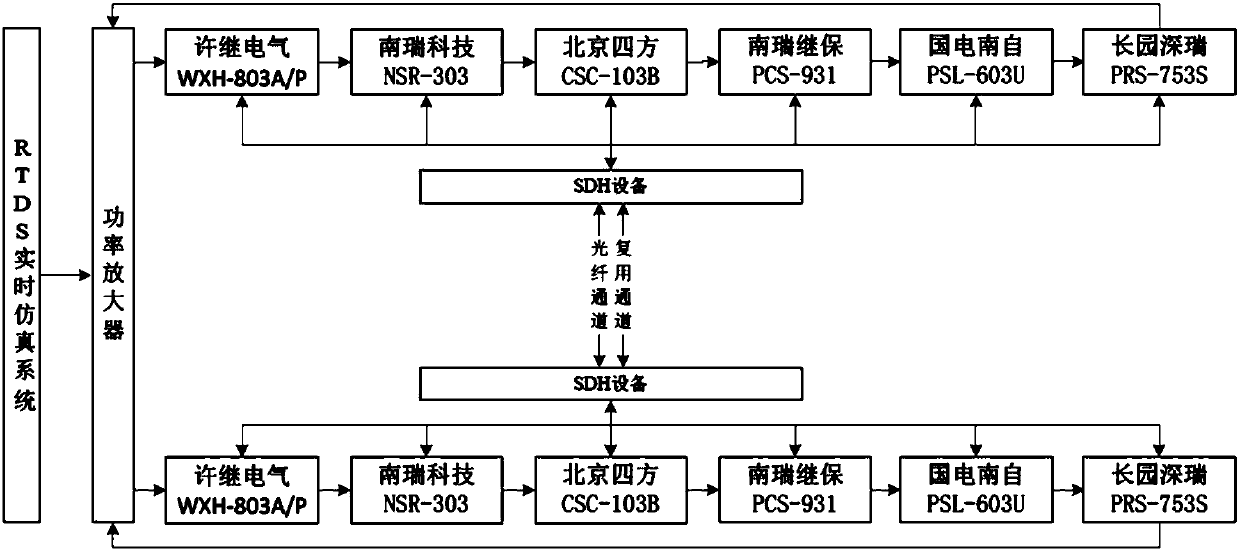
[0044] In a typical implementation of the present application, such as image 3 As shown, relying on the RTDS real-time digital simulation system, a 220kV transmission line longitudinal channel test platform is established.

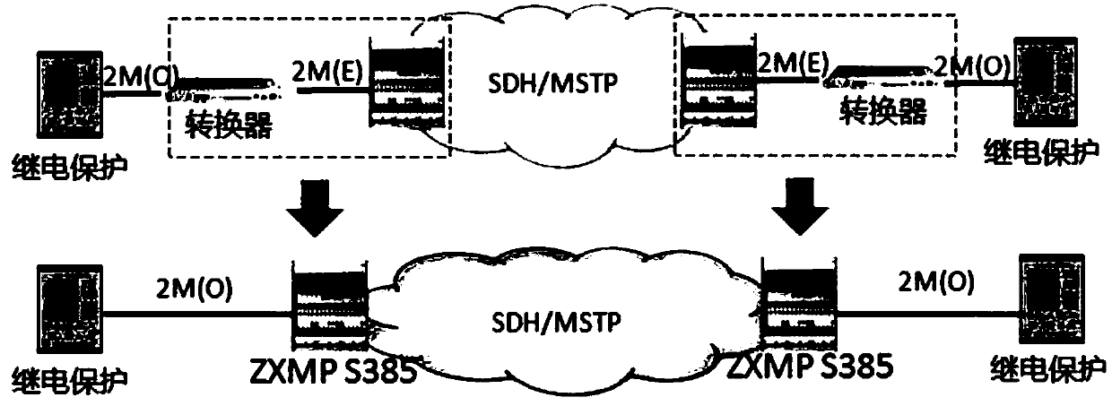
[0045] A joint test system based on a 2M optical interface protection device, the system is based on a pair of transmission equipment equipped with 2M optical interface boards connected by communication, including: point-to-point test verticals connected to the 2M optical interface boards of the transmission equipment at both ends respectively They are all connected to the real-time digital simulation system and the power amplifier in turn, and several corresponding protection devices are connected in parallel to the two test longitudinal channels for joint testing.

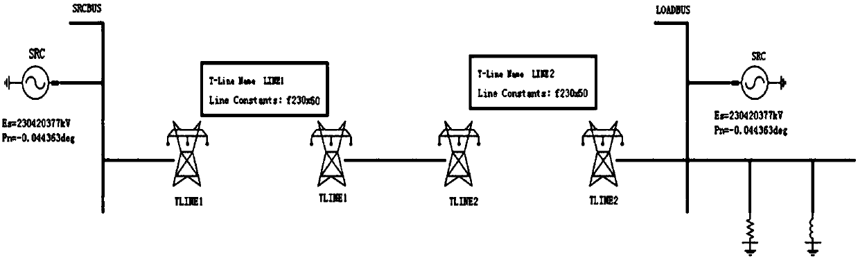
[0046] In this embodiment, the test of the joint test system relies on the RTDS real-time digital simulation system to simulate a 220kV AC system, such as figure 2 As shown, the overhead l...

Embodiment 2

[0060] In a typical implementation manner of the present application, a combined testing method based on a 2M optical interface protection device is provided.

[0061] A joint testing method based on 2M optical interface protection device, the method specifically comprises the following steps:

[0062] Step (1): Connect a 2M optical interface board to be tested and several protection devices into the joint test system;

[0063] Step (2): Carry out at least one joint test between the 2M optical interface board to be tested and several protection devices according to the test requirements;

[0064] Step (3): After the test of the 2M optical interface board to be tested is completed, replace it with the next 2M optical interface board to be tested, and return to step (2) for joint testing until the test is completed for all 2M optical interface boards to be tested.

[0065] As a further preferred solution, in the step (2), according to the test requirements, carry out the alarm ...


PUM


Abstract

The invention relates to a joint test system and method based on a 2M optical interface protection device. The system is based on a pair of transmission devices configured with 2M optical interface boards in communication connection. The system is characterized by comprising point-to-point test longitudinal channels which are respectively connected with 2M optical interface boards of transmissiondevices at two ends and are sequentially connected with a real-time digital simulation system and a power amplifier, and a plurality of corresponding protection devices are sequentially connected in the two test longitudinal channels in parallel for joint test. According to the invention, the efficiency and accuracy of the test system of the 2M optical interface protection device are effectively improved, and the method has a great practical value for the next step of line performance test and popularization.

Description

technical field [0001] The invention belongs to the technical field of substation relay protection, and in particular relates to a joint test system and method based on a 2M optical interface protection device. Background technique [0002] At present, the scale of the power system is increasing with the development of the economy, and the structure is becoming more and more complex. The operation must be safe and reliable, with high power quality and good economy. However, due to the influence of natural conditions, equipment and artificial factors, various failures and abnormal operating conditions may occur. The most common and most harmful faults are various types of short circuits. Faults or abnormal operating conditions may lead to accidents if they are not dealt with in a timely manner. In order to deal with faults and abnormal operating conditions correctly in time and avoid accidents, relay protection is produced. Relay protection mainly uses the change of elect...

Claims


Application Information

Patent Timeline
IPC IPC(8): H04B10/07H04Q11/00
CPCH04B10/07H04Q11/0003H04Q11/0062H04Q2011/0083
Inventor 朱尤祥刘磊田明光于秋生马超王晓勇路振宇王磊周洁王立君徐彬泰吕新荃张彦钟睿田安琪
Owner INFORMATION COMM COMPANY STATE GRID SHANDONG ELECTRIC POWER
Why Eureka
Try Eureka