
Pulse condition acquisition device and pulse condition acquisition system

A technique for acquiring devices and pulse conditions, which is applied in the field of pulse condition acquiring devices and systems, and can solve the problems of slow speed and manpower consumption

Active Publication Date: 2019-09-06
GUANGDONG UNIV OF TECH
View PDF8 Cites 14 Cited by
  • Summary
  • Abstract
  • Description
  • Claims
  • Application Information

AI Technical Summary

Problems solved by technology

This requires that the personnel who collect the pulse condition can accurately judge the position of the inch and the ruler, and the speed is slow and labor-intensive.

Method used


Image

  • Pulse condition acquisition device and pulse condition acquisition system
  • Pulse condition acquisition device and pulse condition acquisition system
  • Pulse condition acquisition device and pulse condition acquisition system

Examples


Embodiment 1

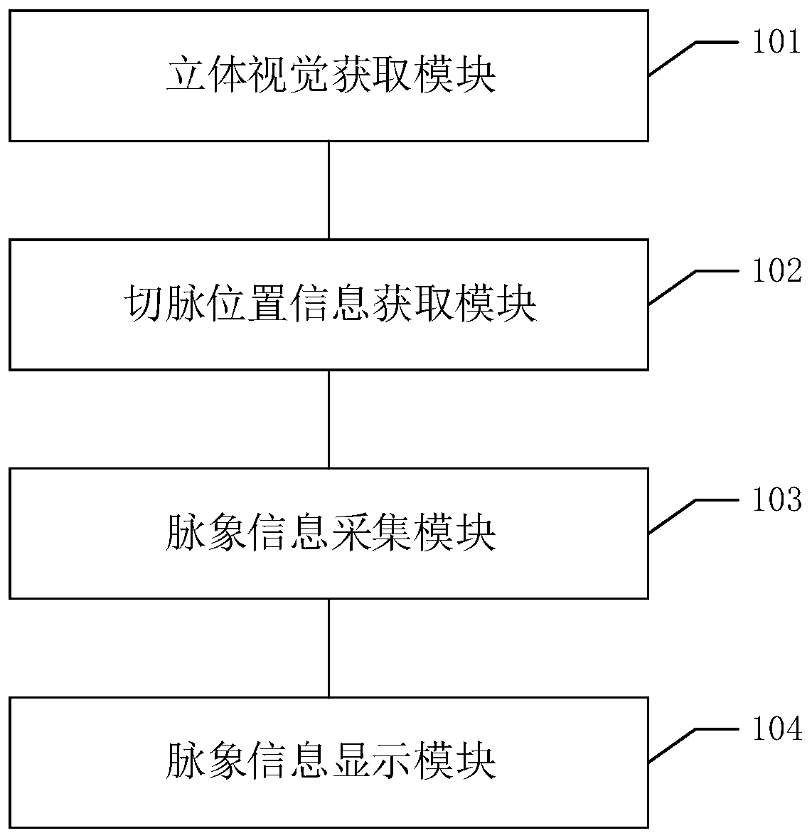
[0043] Please refer to figure 1 , figure 1 It is a schematic structural diagram of a pulse condition acquisition device in an embodiment of the present invention, and the device includes: a stereo vision acquisition module 101, a pulse position information acquisition module 102, a pulse condition information acquisition module 103, and a pulse condition information display module 104;

[0044] Wherein, the stereo vision acquisition module is used to acquire the original image of human wrist with depth information by using a stereo camera.

[0045] In the embodiment of the present invention, the model of the stereo camera is not limited, as long as the stereo camera can obtain the original image of the human wrist with depth information, of course, the obtained original image must meet the definition requirements of computer vision information . In other embodiments of the present invention, two planar cameras may also be used to acquire the original image. Wherein, the ori...

Embodiment 2

[0068] Corresponding to the above method embodiment, the embodiment of the present invention also provides a pulse condition acquisition system, the pulse condition acquisition system described below and the pulse condition acquisition device described above can be referred to each other correspondingly.

[0069] see Figure 4 As shown, the system includes:

[0070] Visual orientation software 101 is installed and the computer 100 that display screen 102 is arranged, has the stereo camera 200 that is connected with computer by communication, has the three-axis motor 300 that is connected by communication with computer, is connected to the pulse diagnosis probe 400 of the output shaft 301 of three-axis motor ;

[0071] Among them, the stereo camera is used to obtain the original image of the human wrist with depth information, and send the original image to the computer;

[0072] The computer is used to use visual positioning software to obtain pulse-cutting position informat...


PUM


Abstract

The invention discloses a pulse condition acquisition device which comprises a stereo vision acquisition module, a pulse diagnosis location information acquisition module, a pulse information collection module and a pulse information display module. The stereo vision acquisition module is used for acquiring original images of human wrists with depth information by using a stereo camera; the pulsediagnosis location information acquisition module is used for inputting the original images into machine learning software to acquire pulse diagnosis location information; the pulse information collection module is used for outputting motor control signals corresponding to the pulse diagnosis location information to a three-axis motor and collecting pulse information by the aid of a pulse diagnosis probe connected to the output shaft of the three-axis motor; the pulse information display module is used for displaying the pulse information on a display screen. In the whole working process to acquire the pulse information, the whole pulse in cun-guan-chi (three places at the wrist where the pulse is usually taken) of patients can be accurately collected without the intervention of doctors. The invention further discloses a pulse condition acquisition system which has the corresponding technical effect.

Description

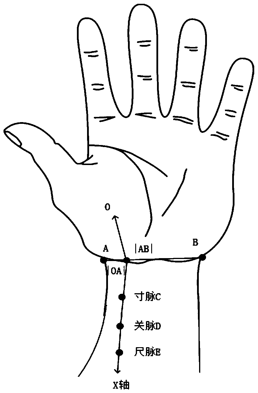
technical field [0001] The invention relates to the technical field of medical devices, in particular to a pulse condition acquisition device and system. Background technique [0002] Chinese medicine diagnoses the cause of disease by feeling the pulse. Pulse-cutting means that the doctor uses his fingers to cut and press the Cun, Guan and Chi parts of the patient's Cunkou radial artery, and perceive the image of the pulse to understand the condition and judge the disease syndrome. The left and right hand Cun Guan Chi represents different organs, that is, the right Cun Lung, the right Cun Spleen, the left Cun Heart, the left Cun Guan Chi, and the left Cun and left Cun are kidneys. In the Cunhou Heart Vessel, if there is fever due to exogenous pathogenic factors, the blood vessels dilate and a floating pulse appears, making the original floating Cun pulse more obvious. The right gate belongs to the spleen, and the left gate belongs to the liver. "Qing·Yizong Jinjian" said: ...

Claims


Application Information

Patent Timeline
Patent Type & Authority Applications(China)
IPC IPC(8): A61B5/02
CPCA61B5/02
Inventor 许淦僖王峰刘立程王宏武潘观潮刘进辉
Owner GUANGDONG UNIV OF TECH
Learn More