Automatic special tooth arc milling machine for chuck jaw

A chuck claw, automatic technology, applied in milling machine equipment, details of milling machine equipment, metal processing machinery parts, etc., can solve the problems affecting the milling arc efficiency of chuck claw, low degree of automation, manual feeding, etc., to achieve structural design. Reasonable, improve the degree of automation, and improve the effect of work efficiency

Pending Publication Date: 2019-09-06
浙江众达机电设备有限公司
View PDF0 Cites 3 Cited by
  • Summary
  • Abstract
  • Description
  • Claims
  • Application Information

AI Technical Summary

Problems solved by technology

[0002] During the preparation process of the chuck claw, it is necessary to use milling arc equipment to process the milling arc. In the prior art, the milling arc equipment generally includes a lathe spindle box and a milling arc cutter head (also called a machine clamp cutter head). , milling arc fixture, X-axis worktable and its drive source, Z-axis worktable and its drive source and guide rails, when in use, fix the jaws on the milling arc fixture, and then drive the milling arc cutter head to the machine through the drive source The claws on the milling arc fixture are used for milling arc processing, but the current conventional milling arc equipment is relatively low in automation, and manual loading and unloading are required during use, which greatly affects the milling arc of the chuck jaws. When the efficiency, can not meet people's requirements

Method used


Image

  • Automatic special tooth arc milling machine for chuck jaw
  • Automatic special tooth arc milling machine for chuck jaw
  • Automatic special tooth arc milling machine for chuck jaw

Examples


Embodiment Construction

[0028] The present invention will now be described in further detail in conjunction with the accompanying drawings.

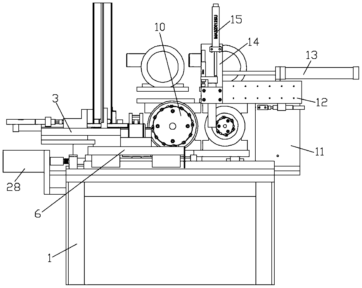
[0029] Such as figure 1 , Figure 7 with Figure 8 As shown, a chuck jaw automatic milling arc special machine includes a bed 1, an automatic feeding mechanism, a clamping mechanism, a cutter head mechanism and an automatic discharging mechanism arranged on the bed 1 in sequence; specifically, as Figure 7 with Figure 8 As shown, when the present invention is not in use, a layer of protective cover can also be set outside the clamping mechanism to protect the clamping mechanism;

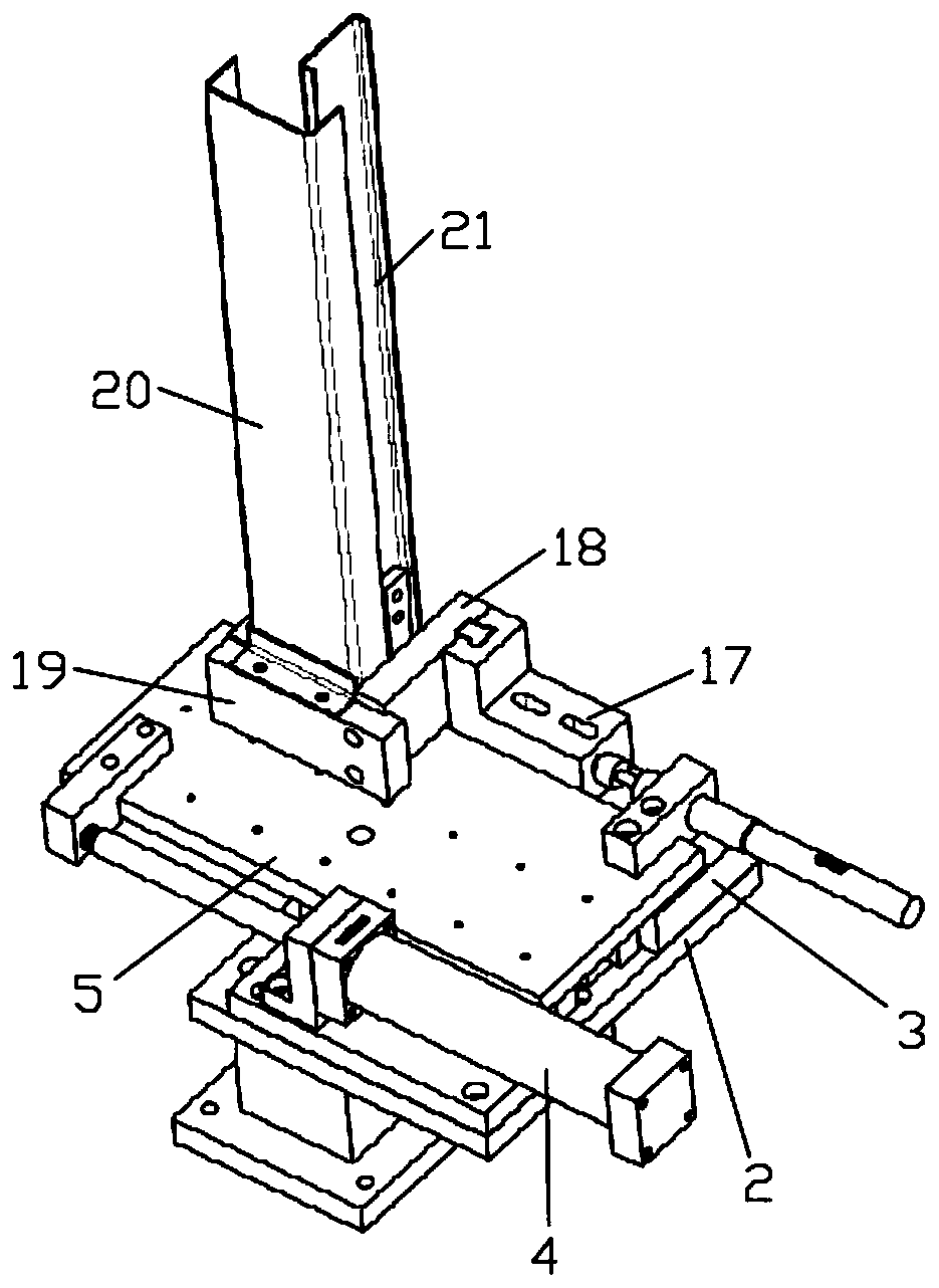
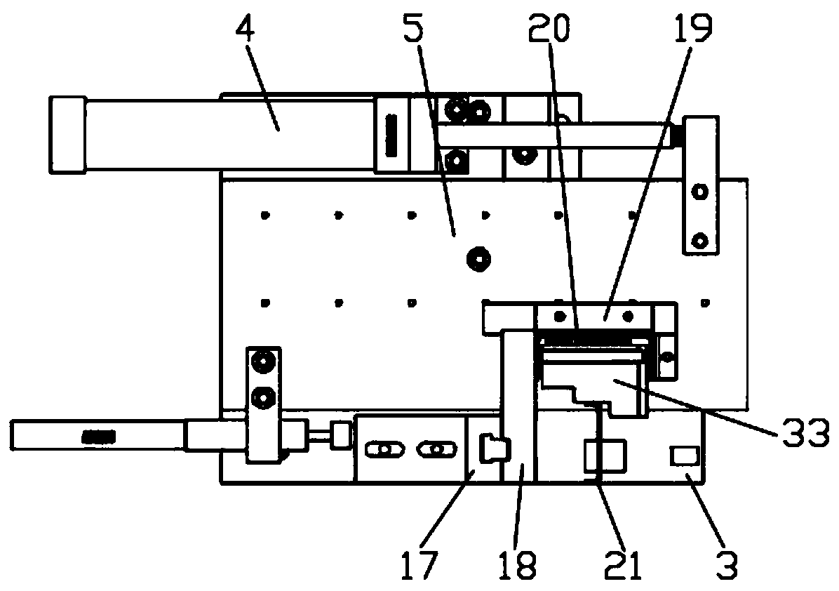
[0030] Such as figure 2 with image 3 As shown, the automatic feeding mechanism includes a feeding base plate 2, a slide table 3, a feed cylinder 4, a slide plate 5 and a feeding rack, the feeding base plate 2 is fixed on the bed 1, and the slide table 3 and The feed cylinders 4 are all fixed on the feeding bottom plate 2, and the bottom of the slide plate 5 slides against the...


PUM


Abstract

The invention discloses an automatic special tooth arc milling machine for a chuck jaw. The automatic special tooth arc milling machine comprises a machine tool bed, and an automatic feeding mechanism, a material clamping mechanism, a cutter mechanism and an automatic discharging mechanism successively arranged on the machine tool bed. The automatic feeding mechanism comprises a charging rack forstacking workpieces, a sliding table for carrying the workpieces, a sliding plate for pushing the workpieces and a feeding air cylinder for providing power to the sliding plate. The automatic discharging mechanism comprises a transverse plate, a transverse air cylinder fixed to the transverse plate, a slide slidably connected to the transverse plate in a clamping manner and connected to the outputend of the transverse air cylinder, a vertical air cylinder fixed to the slide and a sliding needle slidably connected to the slide in a clamping manner and connected to the output end of the vertical air cylinder. The sliding needle and the material clamping plate are located on a same vertical surface, and the bottom end of the sliding needle stretches downward out of the slide. The automatic special tooth arc milling machine provided by the invention is reasonable in structural design and high in degree of automation, and can charge and discharge automatically in use, so that the efficiency of milling the tooth arcs of the chuck jaw is improved greatly.

Description

technical field [0001] The invention relates to the technical field of mechanical processing equipment, in particular to a special machine for automatic milling arcs of chuck jaws. Background technique [0002] During the preparation process of the chuck claw, it is necessary to use milling arc equipment to process the milling arc. In the prior art, the milling arc equipment generally includes a lathe spindle box and a milling arc cutter head (also called a machine clamp cutter head). , milling arc fixture, X-axis worktable and its drive source, Z-axis worktable and its drive source and guide rails, when in use, fix the jaws on the milling arc fixture, and then drive the milling arc cutter head to the machine through the drive source The claws on the milling arc fixture are used for milling arc processing, but the current conventional milling arc equipment is relatively low in automation, and manual loading and unloading are required during use, which greatly affects the mil...

Claims


Application Information

Patent Timeline
Patent Type & Authority Applications(China)
IPC IPC(8): B23C3/00B23Q7/00B23Q3/08
CPCB23C3/00B23Q3/062B23Q3/08B23Q7/00B23Q2703/04
Inventor 田俊杰李建光卢秀果薄小莉刘和
Owner 浙江众达机电设备有限公司
Why Eureka
Try Eureka