
Clamp switching system

A technology for switching systems and fixtures, applied in conveyor objects, transportation and packaging, storage devices, etc., can solve the problems of occupying fixture storage space, occupying a large area, and the production line does not have enough space for installation, etc., and achieve large storage space storage. Space, the effect of simplifying the location of fixtures

Active Publication Date: 2019-09-06
GUANGZHOU MINO AUTOMOTIVE EQUIP CO LTD +1
View PDF9 Cites 1 Cited by
  • Summary
  • Abstract
  • Description
  • Claims
  • Application Information

AI Technical Summary

Problems solved by technology

[0003] At present, most of the tooling and fixture switching methods are to complete the outbound and inbound of fixtures by pulling the fixture trolley set in the fixture warehouse. Among them, the structure of the fixture warehouse is more complicated due to the setting of the fixture trolley, and it is difficult to further realize three-dimensional Moreover, the fixture trolley occupies part of the space of the fixture warehouse, which reduces the utilization rate of the workshop space
[0004] In addition, most of the currently used tooling and fixture switching methods are ground sliding switching. Although the structure is simple, it will occupy too much area when there are many models, resulting in insufficient space for installation in the production line.

Method used


Image

  • Clamp switching system
  • Clamp switching system
  • Clamp switching system

Examples


Embodiment Construction

[0031] This part will describe the specific embodiment of the present invention in detail, and the preferred embodiment of the present invention is shown in the accompanying drawings. Each technical feature and overall technical solution of the invention, but it should not be understood as a limitation on the protection scope of the present invention.

[0032] In the present invention, if there is a description of directions (up, down, left, right, front and back), it is only for the convenience of describing the technical solution of the present invention, rather than indicating or implying that the referred technical features must have specific Orientation, construction and operation in a particular orientation, therefore should not be construed as limiting the invention.

[0033] In the present invention, the meaning of "several" is one or more, and the meaning of "multiple" is more than two. ", "within" and so on are understood as including the original number. In the de...


PUM


Abstract

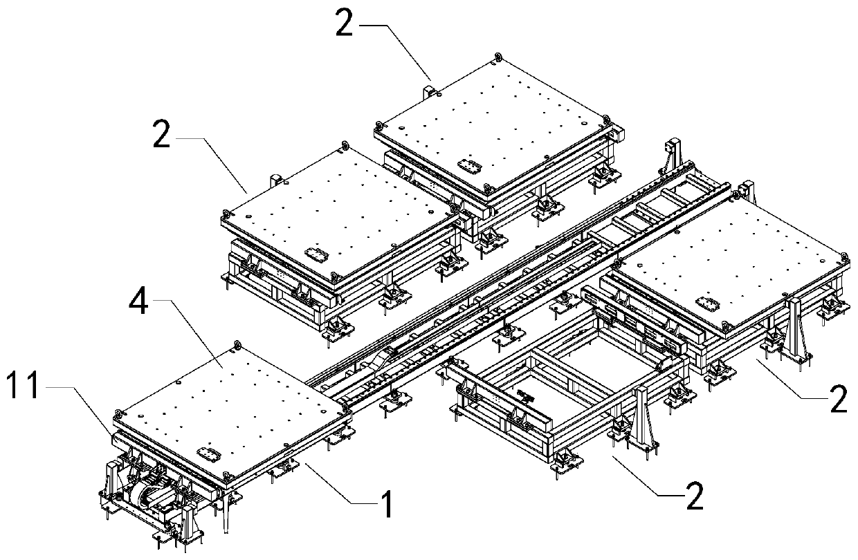
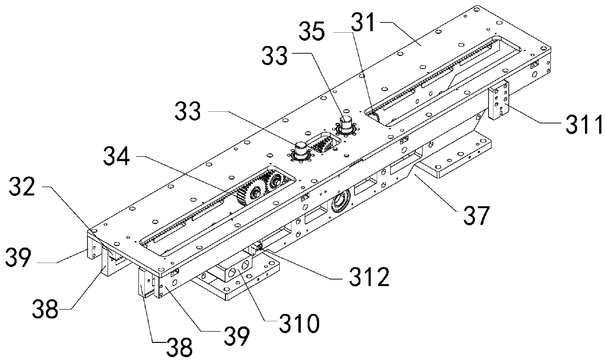
The invention discloses a clamp switching system which comprises a clamp conveying device, a clamp magazine and a traction mechanism. The clamp conveying device comprises a first moving part capable of moving along a clamp conveying path; the traction mechanism comprises a second moving part, gears, a rack and a first driving part, a hitching structure is arranged on the second moving part, the second moving part moves by means of engaged transmission of the gear and the rack, the gears comprise a first gear and a second gear, the first driving part can drive the first gear and the second gearto rotate, the first gear and the second gear are distributed along the length direction of the rack, and the rack is in engaged transmission with the first gear and / or the second gear. The tractionmechanism comprises a first traction mechanism arranged on the first moving part, and the first traction mechanism can be connected to a clamp through the hitching structure and drive the clamp to switch between the first moving part and the clamp magazine. The clamp magazine position is simplified, and a larger magazine position storage space is provided for the clamp.

Description

technical field [0001] The invention is used in the field of clamp switching, and in particular relates to a clamp switching system. Background technique [0002] With the rapid growth of automobile consumption, in order to meet the needs of fast delivery and diversified appearance, automobile manufacturing technology has gradually realized a high degree of automation, and the single-model production line has been transformed into a multi-model shared production line. With the continuous improvement of diversified needs, the positioning and clamping positions of parts vary greatly, resulting in more and more fixtures in the production line. [0003] At present, most of the tooling and fixture switching methods are to complete the outbound and inbound of fixtures by pulling the fixture trolley set in the fixture warehouse. Among them, the structure of the fixture warehouse is more complicated due to the setting of the fixture trolley, and it is difficult to further realize th...

Claims


Application Information

Patent Timeline
Patent Type & Authority Applications(China)
IPC IPC(8): B65G1/04B65G47/90
CPCB65G1/04B65G47/902
Inventor 丘邦超柯晓鸿王斌李德恒杨猛陈振城黄凯东
Owner GUANGZHOU MINO AUTOMOTIVE EQUIP CO LTD
Learn More