A hanging translation device based on fiber laser

A technology of fiber laser and translation device, which is applied in the direction of transportation and packaging, load suspension components, load pulleys, etc., and can solve the problems of unfavorable complex line cargo transportation, unfavorable hoisting use, and inability to flexibly adjust hoisting devices.

Active Publication Date: 2020-10-30
泉州台商投资区钰宝商贸有限公司
View PDF5 Cites 0 Cited by
  • Summary
  • Abstract
  • Description
  • Claims
  • Application Information

AI Technical Summary

Problems solved by technology

[0002] Hoisting refers to the general term for the installation and positioning of equipment by cranes or lifting mechanisms. During the process of overhaul or maintenance, various hoisting tools are used to lift equipment, workpieces, appliances, materials, etc., to change their positions. In many fields It must be widely used. At present, there are a large number of hoisting devices on the market, which have the advantages of convenient operation, firm structure, easy movement, high economy, high work efficiency, and simple maintenance. They can meet the hoisting and transportation of most equipment and goods. However, for most of the hoisting devices, on the one hand, they cannot be positioned accurately during use, because the operator needs to operate near the hoisting equipment, and needs to be controlled by other personnel to control the movement of the object, so the operation There is a certain delay, and it is easy to cause improper hoisting of items due to improper command. On the other hand, when transporting goods, when there are other equipment or goods on the delivery route as obstacles, it is difficult to control and is not conducive to complex operations. On the other hand, the cargo transportation of the line cannot be flexibly adjusted according to the resistance of the hoisting device itself during rotation, which is not conducive to hoisting use

Method used


Image

  • A hanging translation device based on fiber laser
  • A hanging translation device based on fiber laser
  • A hanging translation device based on fiber laser

Examples


Embodiment approach

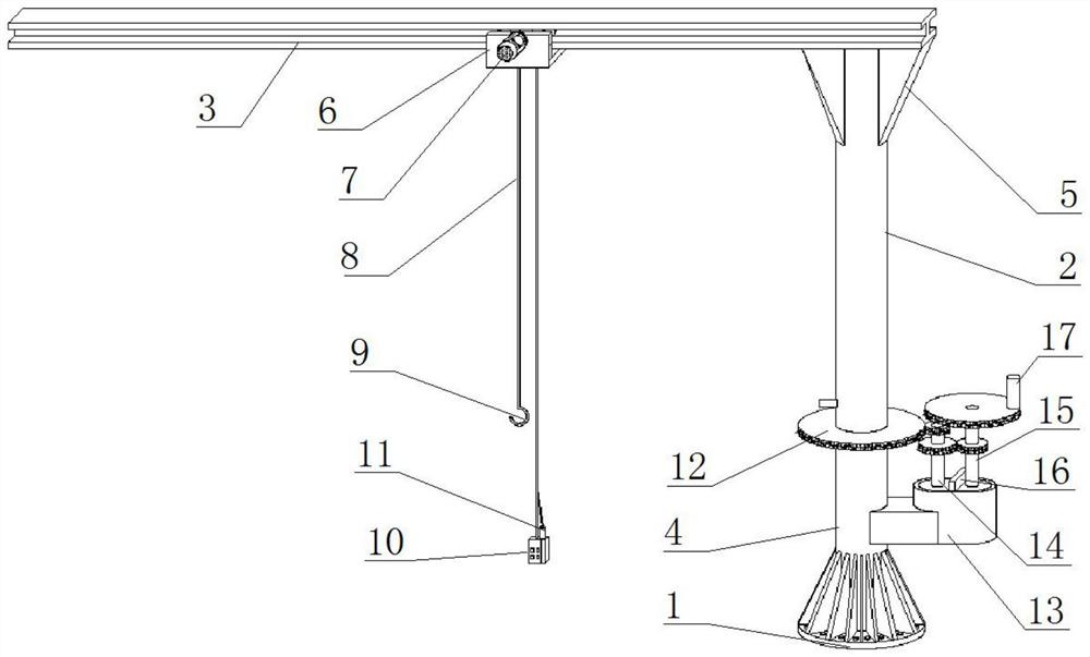
[0030]As a preferred embodiment of the present invention, the first gear set 14 is welded on the output shaft of the third motor 28, the driving wheel 18 is welded on the output shaft of the first motor 7, and the reel 21 is welded on the second motor 20. on the output shaft.

[0031] As a preferred embodiment of the present invention, the first gear set 14 is installed on the top of the clamping plate 27 through a rotating shaft, the first gear set 14 meshes with the second gear set 15 and the gear 12, and the second gear set 15 and The gears 12 mesh.

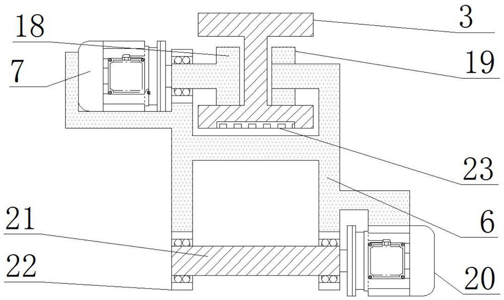
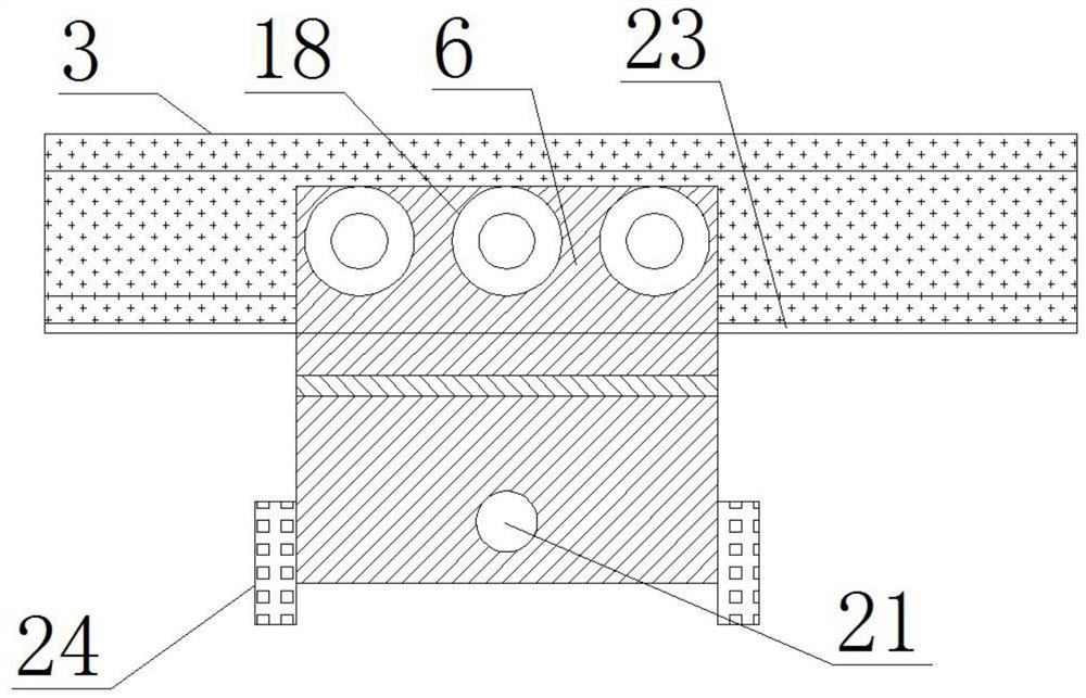
[0032] As a preferred embodiment of the present invention, both the driving wheel 18 and the roller 19 are stuck inside the I-beam 3 , and the driving wheel 18 is mounted on the movable frame 6 through a bearing 22 .

[0033] As a preferred embodiment of the present invention, a stopper 16 is welded on the top of the fixing sleeve 13 , and the stopper 16 is matched with the clamping plate 27 .

[0034] As a preferred embodim...


PUM


Abstract

The invention provides a hauling translation device based on an optical fiber laser. The hauling translation device comprises a base, a fulcrum rod and an I beam. A cutting sleeve is welded to the topof the base, the fulcrum rod is mounted on the top of the cutting sleeve through a rotary shaft, the I beam is welded to the top of the fulcrum rod through supports, a movable frame is clamped to theI beam, a first motor is welded to one side of the movable frame, a lifting rope is arranged at the bottom of the movable frame, the bottom of the lifting rope is connected with a hook, a controlleris arranged at the bottom of the movable frame, the optical fiber laser is arranged on the controller, a gear is welded to the outer side of the fulcrum rod, a first gear set is arranged on one side of a second gear set, a handle is welded to the top of the second gear set, a movable wheel is welded to one side of the first motor, a roller is welded to the top of the movable frame, and a second motor is welded to the bottom of the movable frame. The hauling translation device based on the optical fiber laser is reasonable in design, convenient to use and suitable for hauling translation of cargo equipment.

Description

technical field [0001] The invention relates to the field of optical fiber suspension translation equipment, in particular to a suspension translation device based on a fiber laser. Background technique [0002] Hoisting refers to the general term for the installation and positioning of equipment by cranes or lifting mechanisms. During the process of overhaul or maintenance, various hoisting tools are used to lift equipment, workpieces, appliances, materials, etc., to change their positions. In many fields It must be widely used. At present, there are a large number of hoisting devices on the market, which have the advantages of convenient operation, firm structure, easy movement, high economy, high work efficiency, and simple maintenance. They can meet the hoisting and transportation of most equipment and goods. However, for most of the hoisting devices, on the one hand, they cannot be positioned accurately during use, because the operator needs to operate near the hoisting...

Claims


Application Information

Patent Timeline
Patent Type & Authority Patents(China)
IPC IPC(8): B66C11/04B66C11/16B66C13/08B66C13/16
CPCB66C11/04B66C11/16B66C13/08B66C13/16B66C23/62B66C23/84
Inventor 林建铃
Owner 泉州台商投资区钰宝商贸有限公司
Why Eureka
Try Eureka