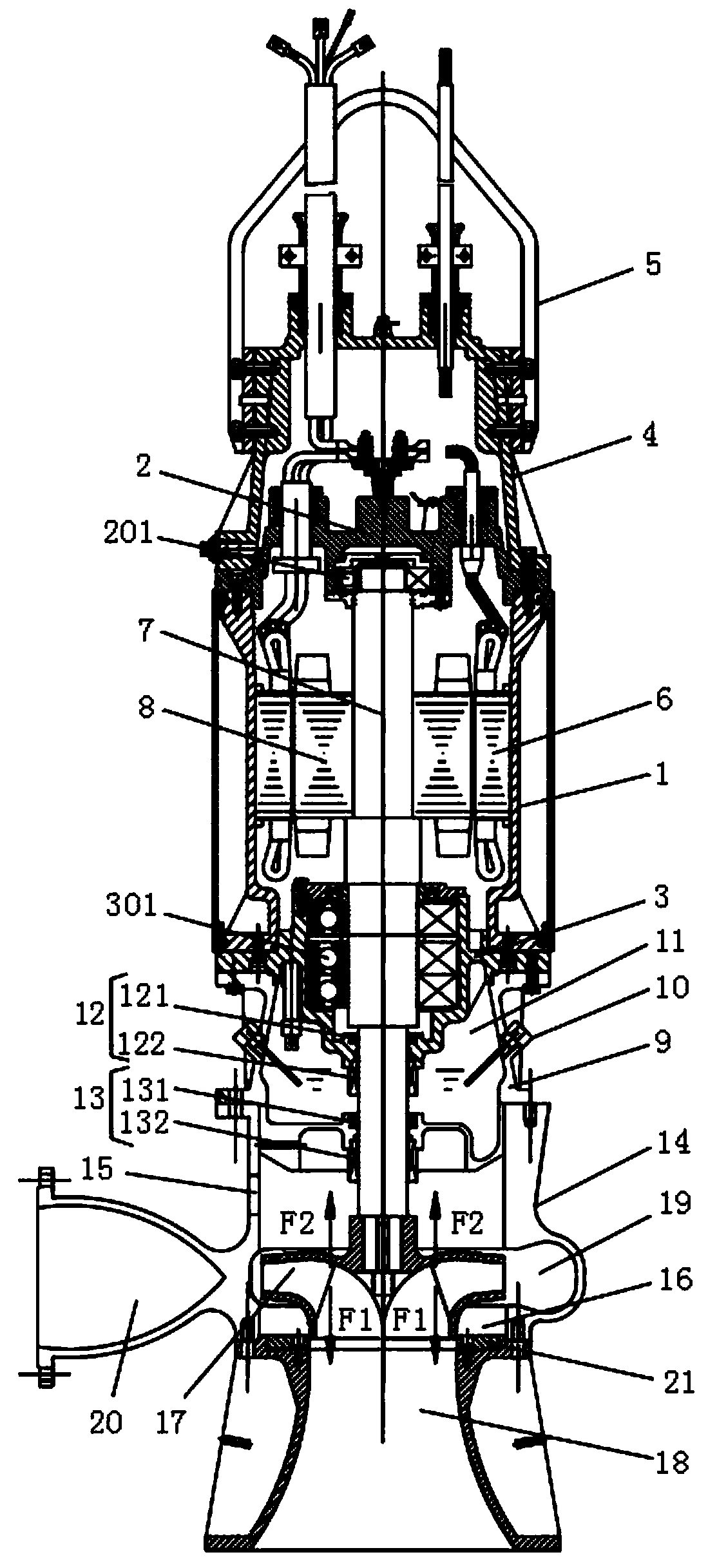
Double sucking type submersible pump

A submersible pump, double-suction technology, applied in the field of double-suction submersible pumps, can solve the problems of accelerated wear, reduced bearing service life, abnormal failure of mechanical seals, etc.

Pending Publication Date: 2019-09-06
ANHUI ZHENGYUAN MACHINERY
View PDF0 Cites 0 Cited by
  • Summary
  • Abstract
  • Description
  • Claims
  • Application Information

AI Technical Summary

Problems solved by technology

[0004] During the installation and use of the unbalanced mechanical seal, because the unbalanced mechanical seal is only suitable for low pressure, otherwise it will cause accelerated wear and cause abnormal failure of the mechanical seal, thus making the design flow and head of the submersible pump lower; When the impeller is working, since the delivered liquid enters the impeller from the bottom of the pump, the action of the liquid passing through the impeller will generate a downward axial force on the impeller. Under the same flow rate, the higher the head, the greater the axial force generated , because the commonly used submersible pumps do not have an axial force balance device, the axial force generated will act on the bearings in the submersible pump, thereby reducing the service life of the bearings, so the traditional submersible pump cannot be used for large flow and high lift send liquid

Method used


Image

  • Double sucking type submersible pump

Examples


Embodiment Construction

[0018] The following will clearly and completely describe the technical solutions in the embodiments of the present invention with reference to the accompanying drawings in the embodiments of the present invention. Obviously, the described embodiments are only some, not all, embodiments of the present invention.

[0019] In describing the present invention, it should be understood that the terms "upper", "lower", "front", "rear", "left", "right", "top", "bottom", "inner", " The orientation or positional relationship indicated by "outside", etc. is based on the orientation or positional relationship shown in the drawings, and is only for the convenience of describing the present invention and simplifying the description, rather than indicating or implying that the referred device or element must have a specific orientation, so as to Specific orientation configurations and operations, therefore, are not to be construed as limitations on the invention.

[0020] refer to figure 1...


PUM


Abstract

The invention discloses a double sucking type submersible pump. An installing barrel is included; an upper end cover is installed at the upper end of the installing barrel, and a lower end cover is installed at the lower end of the installing barrel; an oil shell is fixedly installed on the surface of the outer side of the exterior of the lower end cover; a volute is fixedly installed at the lowerend of the oil shell; a stator iron core is installed on the middle portion of the inner ring face of the installing barrel; a magnet rotor is arranged at the center of the stator iron core; a middleshaft is fixedly arranged at the center of the magnet rotor in a penetrating manner; the lower end of the middle shaft penetrates through the lower end cover and the center of the oil shell and extends into the volute; the end portion, located in the volute, of the middle shaft is provided with an impeller; a shell of one side, located above the impeller, of the volute is provided with a first water inlet, and a second water inlet is formed in the lower end of the volute; the position of the second water inlet is provided with a horn opening; a water outflow channel is formed at the position,corresponding to the outer side of the impeller, of the volute; and the side, the same as the first water inlet, on the water outflow channel is provided with a water outlet. The submersible pump canbe used for pumping liquid at a large flow and high lift, and can be easily used and popularized.

Description

technical field [0001] The invention relates to the technical field of submersible pumps, in particular to a double-suction submersible pump. Background technique [0002] At present, the traditional submersible pump adopts a single-suction impeller in structure, and the way of bottom-in and side-out, that is, the transported liquid enters the impeller from the bottom of the pump, is pressurized by the impeller, and is discharged from the water outlet on the side of the pump. [0003] Traditional submersible pumps usually use two sets of unbalanced mechanical seals in series, one set is installed in the high pressure area on the back of the impeller, directly in contact with the conveying liquid, and the other is installed in the oil chamber to prevent the conveying liquid from entering the motor and burning the motor. [0004] During the installation and use of the unbalanced mechanical seal, because the unbalanced mechanical seal is only suitable for low pressure, otherwis...

Claims


Application Information

Patent Timeline
Patent Type & Authority Applications(China)
IPC IPC(8): F04D13/08F04D29/046F04D29/08F04D29/42
CPCF04D13/08F04D29/046F04D29/086F04D29/426F04D29/4273
Inventor 张王徽胡晓飞陈建杨林丁陈民陆保文杨多萍朱晓苏
Owner ANHUI ZHENGYUAN MACHINERY
Why Eureka
Try Eureka