Force measuring method of ventilation model under condition of free jet wind tunnel test

A wind tunnel test and model technology, applied in aerodynamic tests, measuring devices, machine/structural component testing, etc., can solve problems such as inability to fully simulate the real flight environment of the aircraft, inaccurate model force measurement, etc., to improve performance Analysis of technology and capabilities, and the effect of filling technology gaps

Inactive Publication Date: 2019-09-06
BEIJING AEROSPACE TECH INST
View PDF7 Cites 22 Cited by
  • Summary
  • Abstract
  • Description
  • Claims
  • Application Information

AI Technical Summary

Problems solved by technology

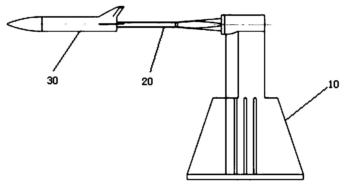
[0004] The purpose of the present invention is to overcome the deficiencies in the prior art, to provide a method for measuring the force of a ventilation model under the test conditions of a free-jet wind tunnel, which can solve the problem that the conventional wind tunnel in the prior art cannot fully simulate the real flight environment of the aircraft. Technical problems such as inaccurate model force measurement

Method used


Image

  • Force measuring method of ventilation model under condition of free jet wind tunnel test
  • Force measuring method of ventilation model under condition of free jet wind tunnel test
  • Force measuring method of ventilation model under condition of free jet wind tunnel test

Examples


Embodiment Construction

[0047] It should be noted that, in the case of no conflict, the embodiments in the present application and the features in the embodiments can be combined with each other. The following will clearly and completely describe the technical solutions in the embodiments of the present invention with reference to the accompanying drawings in the embodiments of the present invention. Obviously, the described embodiments are only some, not all, embodiments of the present invention. The following description of at least one exemplary embodiment is merely illustrative in nature and in no way taken as limiting the invention, its application or uses. Based on the embodiments of the present invention, all other embodiments obtained by persons of ordinary skill in the art without creative efforts fall within the protection scope of the present invention.

[0048] It should be noted that the terminology used here is only for describing specific implementations, and is not intended to limit t...


PUM


Abstract

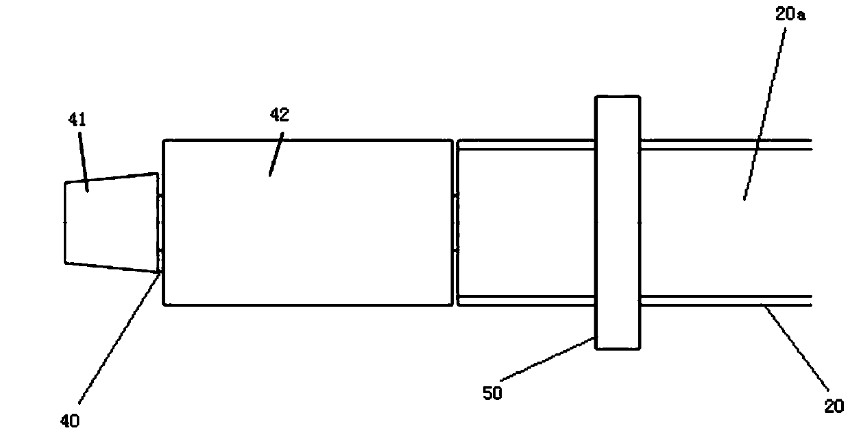
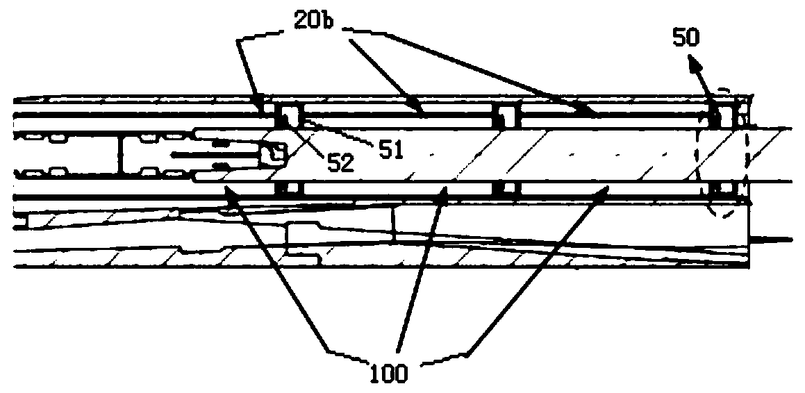
The invention provides a force measuring method of a ventilation model under the condition of a free jet wind tunnel test. The force measuring method of the ventilation model under the condition of the free jet wind tunnel test comprises the following steps that a ventilation model force measuring device is designed, specifically, the ventilation model, a measurement balance, a base, a tail support rod and a hot air flow blocking assembly are included, wherein the measurement balance is arranged in the ventilation model and used for measuring the aerodynamic performance of the ventilation model; the tail support rod realizes the supporting of the ventilation model in a tail support mode, one end of the tail support rod is arranged on the base, the other end of the tail support rod is connected with the measurement balance, and the tail support rod is not in contact with the inner wall of the ventilation model; the hot air flow blocking assembly is arranged between the tail support rodand the inner wall of the ventilation model, so that the tail support rod and the inner wall of the ventilation model are not in contact, and the hot air flow blocking assembly is used for reducing the flow velocity of hot air flow entering the tail of the ventilation model in the ventilation model; the ventilation model force measuring device is placed in a free jet wind tunnel; and the wind tunnel test is carried out to obtain effective force measuring data. According to the force measuring method of the ventilation model under the condition of the free jet wind tunnel test, the technical problems such as the inaccuracy of the model force measuring due to the inability to completely simulate the real flight environment of an aircraft in a conventional wind tunnel in the prior art can besolved.

Description

technical field [0001] The invention relates to the technical field of aircraft aerodynamic performance prediction, in particular to a ventilation model force measurement method under free-jet wind tunnel test conditions. Background technique [0002] Thrust-drag matching is the core issue of whether the overall plan of the aircraft is established or not. The most typical feature of an aircraft designed using the airframe / propulsion integration method is the high coupling of internal and external flows, which makes it difficult to predict and analyze its integrated aerodynamic performance and thrust-drag characteristics. Therefore, it is a key problem that must be solved in the development of this type of aircraft to develop wind tunnel test technology and improve the prediction accuracy and ability of aerodynamic performance of aircraft coupled with internal and external flow. At present, the conventional wind tunnels that can be used to obtain the performance of high-spee...

Claims


Application Information

Patent Timeline
Patent Type & Authority Applications(China)
IPC IPC(8): G01M9/06
CPCG01M9/06G01M9/062
Inventor 汤继斌黄海生卢志毅王立宁
Owner BEIJING AEROSPACE TECH INST
Why Eureka
Try Eureka