High-efficiency end face light guide plate for backlight module and preparation process thereof

A technology of backlight module and light guide plate, applied in the direction of light guide, flat/plate light guide, light guide of lighting system, etc., can solve the problems of unreasonable setting of dots, not enough green environmental protection, high toxicity of chloroform, etc., to increase scattered light and mixed light The effect, the uniform effect of light output is good, the effect of increasing the diffusion range

Active Publication Date: 2019-09-06
INNER MONGOLIA ZHONGSEN SMART TERMINAL R & D CO LTD
View PDF16 Cites 2 Cited by
  • Summary
  • Abstract
  • Description
  • Claims
  • Application Information

AI Technical Summary

Problems solved by technology

[0004] After a comprehensive study of the existing light guide plates for backlight modules and their preparation techniques, there are still the following problems to be solved: 1. The dots on the light guide plate are not properly set up, including their density and size, which cannot make the light guide plate play a good role. Light effect; 2. The ink required for printing contains a large amount of volatile solvents, which has certain toxicity, is not environmentally friendly, and will cause harm to the human body during production and use; 3. When etching dot slots, the etching The liquid is chloroform, first of all, chloroform is highly toxic, and secondly, if there is any residue in production, it will gradually oxidize under light to form highly toxic phosgene, which brings serious safety problems

Method used


Image

  • High-efficiency end face light guide plate for backlight module and preparation process thereof
  • High-efficiency end face light guide plate for backlight module and preparation process thereof
  • High-efficiency end face light guide plate for backlight module and preparation process thereof

Examples


Embodiment 1

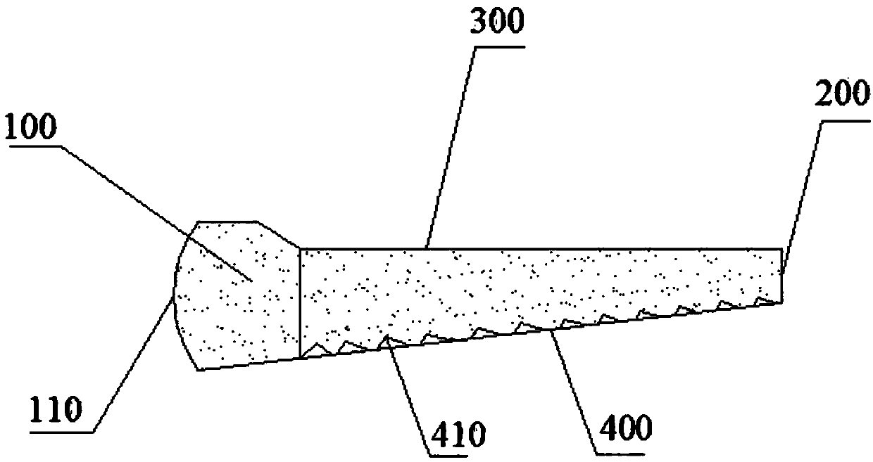
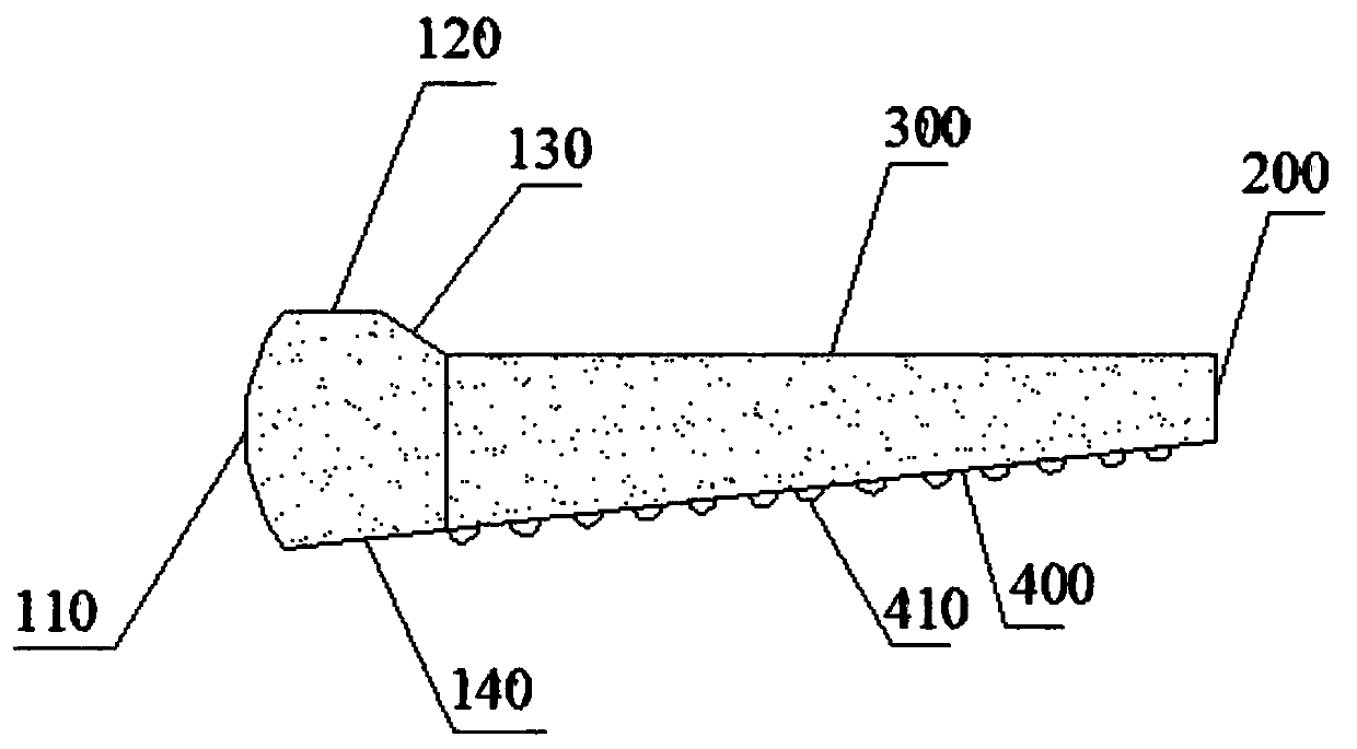
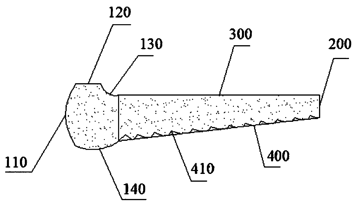
[0035] see Figure 1-5 As shown, this embodiment provides a high-efficiency end-surface light guide plate for a backlight module, including a light-incident surface 100, a light-guiding end-surface 200 opposite to the light-incident surface 100, and a connection between the light-incident surface 100 and the light-guiding end surface 200 The light exit surface 300 is connected to the light incident surface 100 and the light guide surface 400 of the light guide end surface 200 . The light emitting surface 300 is horizontal, the light guiding end surface 200 is vertical, and the light guiding surface 400 is oblique.

[0036]Specifically, the light incident surface 100 includes an upper surface, a lower surface 140, and a light incident end surface 110, one end of the light incident end surface 110 is connected to the upper surface, and the other end is connected to the lower surface 140; the other end of the upper surface is connected to the light exit surface 300, The other en...

Embodiment 2

[0040] The high-efficiency end-surface light guide plate for a backlight module of this embodiment is suitable for a backlight module. refer to Figure 5 As shown, in addition to the light guide plate 1, the backlight module also includes a back plate 2, a reflective sheet 3 disposed on the back plate 2, an LED light source 4 disposed on the side wall of the back plate 2, and a light source disposed on the light guide plate 1. The optical film group is arranged on the plastic frame 5 on both sides of the back plate 2 . The LED light source 4 corresponds to the light incident surface of the light guide plate 1 , and the optical film set includes an upper diffusion sheet 6 , a prism sheet 7 , and a lower diffusion sheet 8 arranged in sequence from top to bottom. The working process of the backlight module is as follows: turn on the LED light source 4, the LED light source is a line light source, the light emitted enters from the light incident surface of the light guide plate 1...

Embodiment 3

[0042] This embodiment provides a preparation process of a high-efficiency end-face light guide plate for a backlight module, including the following steps:

[0043] S1. Light guide plate mold preparation: Design the light guide plate mold according to the light guide plate to be produced. The light guide plate mold is a hollow structure composed of a light entrance mold surface, a light exit mold surface, a light guide mold surface, and a light guide end mold surface. An injection port is provided on the end mold surface, and the light entrance mold surface, the light exit mold surface, the light guide mold surface, and the light guide end mold surface correspond to the light entrance surface 100, the light exit surface 300, the light guide surface 400, and the light guide end surface 200, respectively. The surface of the light guide mold is provided with a convex mold surface corresponding to the protrusion 410; wherein, the thickness of the light guide plate mold is 5-10mm, ...


PUM

PropertyMeasurementUnit
Thicknessaaaaaaaaaa

Abstract

The invention discloses a high-efficiency end face light guide plate for a backlight module and a preparation process thereof. The high-efficiency end face light guide plate for the backlight module includes a light incident face, a light guide end face disposed opposite to the light incident face, a light exit face connecting the light incident face and the light guide end face, and a light guideface connecting the light incident face and the light guide end face; the light exit face is horizontal, the light guide end face is vertical, and the light guide face is inclined; the light incidentface includes an upper surface, a lower surface, and a light incident end face; one end of the light incident end face is connected to the upper surface, and the other end is connected to the lower surface; the other end of the upper surface is connected to the light exit face, and the other end of the lower surface is connected to the light guide face; and the upper surface includes a horizontalsection adjacent to the light incident end face and an inclined section away from the light incident end face. The light guide plate is prepared by a mold injection molding method. The light guide plate disclosed by the invention increases the diffusion angle and the diffusion range of the light, increases the scattering and light mixing effect, and has uniform light output and good effect; and the preparation process is non-toxic and high-efficiency, which is suitable for industrial production.

Description

technical field [0001] The invention relates to the field of display technology, in particular to a high light efficiency end face light guide plate for a backlight module and a preparation process thereof. Background technique [0002] With the continuous development and maturity of liquid crystal display technology, liquid crystal display gradually occupies a dominant position in the flat panel display market. The backlight module is a backlight component in liquid crystal display products, and generally consists of a backlight source, a multi-layer backlight material and a supporting frame. The quality of the backlight determines important parameters such as the brightness of the LCD screen, the uniformity of the emitted light, and the color scale. The light guide plate is an important structure in the backlight module. It is used to convert the line light source of the backlight into a surface light source with uniform brightness, which improves the uniformity of light ...

Claims


Application Information

Patent Timeline
IPC IPC(8): G02B6/00G02F1/13357
CPCG02B6/002G02B6/0036G02B6/0046G02B6/0065G02F1/133615
Inventor 不公告发明人
Owner INNER MONGOLIA ZHONGSEN SMART TERMINAL R & D CO LTD
Why Eureka
Try Eureka