
Display panel, driving method thereof and display device

A technology of display panel and driving method, applied in static indicators, instruments, etc., can solve the problem of insufficient pixel charging of display products, and achieve the effect of increasing pixel charging time

Inactive Publication Date: 2019-09-06
BOE TECH GRP CO LTD
View PDF11 Cites 6 Cited by
  • Summary
  • Abstract
  • Description
  • Claims
  • Application Information

AI Technical Summary

Problems solved by technology

[0004] In view of this, an embodiment of the present invention provides a display panel, its driving method and a display device to solve the problem of insufficient charging of pixels in existing display products

Method used


Image

  • Display panel, driving method thereof and display device
  • Display panel, driving method thereof and display device
  • Display panel, driving method thereof and display device

Examples


Embodiment Construction

[0031] In order to make the purpose, technical solution and advantages of the present invention clearer, the specific implementation manners of the display panel, its driving method and the display device provided by the embodiments of the present invention will be described in detail below with reference to the accompanying drawings. It should be understood that the preferred embodiments described below are only used to illustrate and explain the present invention, not to limit the present invention. And in the case of no conflict, the embodiments in the present application and the features in the embodiments can be combined with each other.

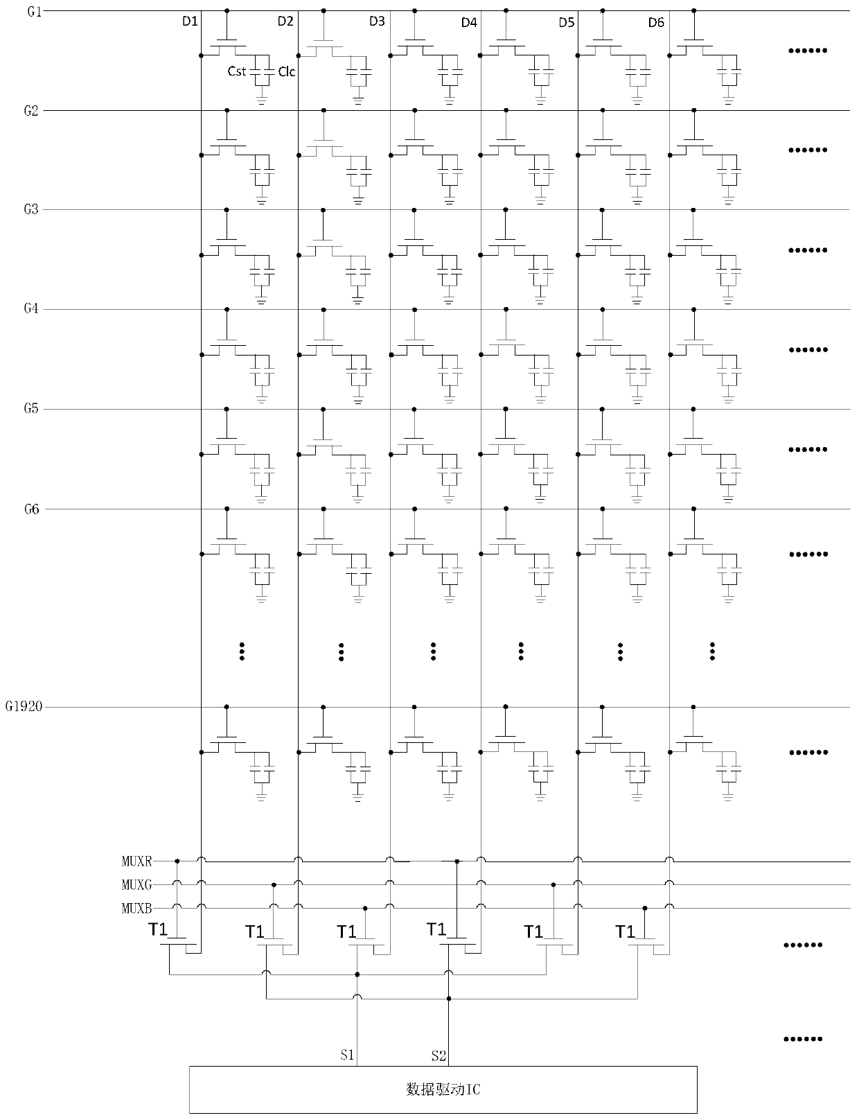
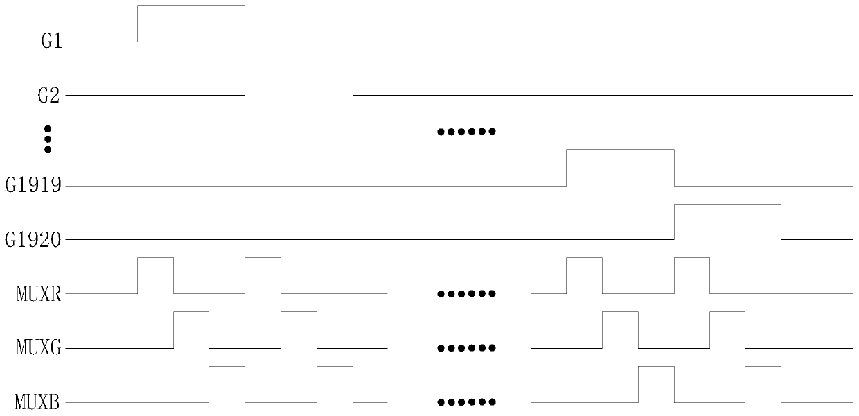
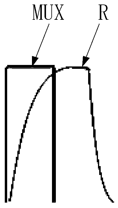
[0032] Such as figure 1 as shown, figure 1 It is a schematic diagram of a circuit using 3-MUX to charge pixels in the prior art, figure 1 The labels MUXR, MUXG, and MUXB are used to indicate the three MUX control signal lines corresponding to the sub-pixel columns of different colors, and the first switching transistor T1 correspondin...


PUM


Abstract

The invention discloses a display panel, a driving method thereof and a display device. Pre-charging control circuits in one-to-one correspondence with MUX signal input circuits are arranged; each pair of corresponding MUX signal input circuit and pre-charging control circuit are electrically connected with the same preset number of data lines; in a grid line scan period, when the MUX signal inputcircuit loads data voltage to the first data line, the pre-charging control circuit loads a pre-charging voltage to at least one second data line. When the MUX signal input circuit sequentially loadsthe data voltage to the second data line, the pixel charging time corresponding to the second data line can be additionally increased on the basis of the pixel charging time provided by the prior artdue to the fact that the second data line loads the pre-charging voltage in advance.

Description

technical field [0001] The present invention relates to the field of display technology, in particular to a display panel, a driving method thereof and a display device. Background technique [0002] At present, the data driving chip in the display outputs the pixel voltage to the pixel unit through the data line. Due to the large number of data lines in the display, correspondingly, the data driver chip needs more pins, so there are correspondingly more data transmission lines for transmitting data signals to each data line, which is not conducive to realizing a narrow frame of the display. In order to achieve a full screen, by reducing the number of data transmission lines, a MUX signal input circuit is set between the data driver chip and the data lines in the related art. At present, the commonly used solution is that the data driver chip can connect three sub-pixel units RGB through the MUX (which can be called 1:3MUX solution), and the data driver chip can connect six...

Claims


Application Information

Patent Timeline
Patent Type & Authority Applications(China)
IPC IPC(8): G09G3/36G09G3/3275
CPCG09G3/3688G09G3/3275G09G3/3648
Inventor 宗少雷孙伟孙继刚
Owner BOE TECH GRP CO LTD
Learn More