
A multifunctional visual laryngoscope

A multifunctional and laryngoscope technology, applied in the field of multifunctional visual laryngoscope, can solve problems such as uncomfortable spraying, affecting the efficiency of intubation and the success rate of rescue, reducing the visibility of the larynx, etc., to solve the problem of temperature influence, use Safety and convenience, multi-functional effect

Active Publication Date: 2021-08-27
THE SECOND HOSPITAL AFFILIATED TO WENZHOU MEDICAL COLLEGE
View PDF7 Cites 0 Cited by
  • Summary
  • Abstract
  • Description
  • Claims
  • Application Information

AI Technical Summary

Problems solved by technology

[0003] However, the laryngoscope of the prior art has the following disadvantages when checking the larynx: because the video laryngoscope transmits and enlarges the image to the display through the camera, it is easily affected by the temperature difference of the respiratory tract and airway secretions, etc., causing the front end of the camera to The surface forms a condensation film or is covered by secretions, reducing the visibility of the larynx, thereby affecting the efficiency of intubation and the success rate of rescue
[0005] However, the visual laryngoscope with oxygen channel of the above-mentioned technical solution has: the viscosity of laryngeal secretions is strong, and after the lens contacts the secretions or is covered by the secretions, it is difficult to remove them by jet airflow, and the throat It belongs to very important tissues and organs of the human body. In order to avoid damage, it is not suitable for spraying large airflows. Therefore, this solution cannot effectively improve the clarity of the exposed field of view; at the same time, simply selecting LED lights to reduce the temperature impact on the lens cannot Fundamentally control the heating of the lighting lamp, that is, the problem of the temperature influence on the lens cannot be fully solved

Method used


Image

  • A multifunctional visual laryngoscope
  • A multifunctional visual laryngoscope
  • A multifunctional visual laryngoscope

Examples


Embodiment Construction

[0034] In order to make the object, technical solution and advantages of the present invention clearer, the present invention will be further described in detail below in conjunction with the accompanying drawings.

[0035] It should be noted that, unless otherwise specified, the technical terms or scientific terms used in this application shall have the usual meanings understood by those skilled in the art to which the present invention belongs.

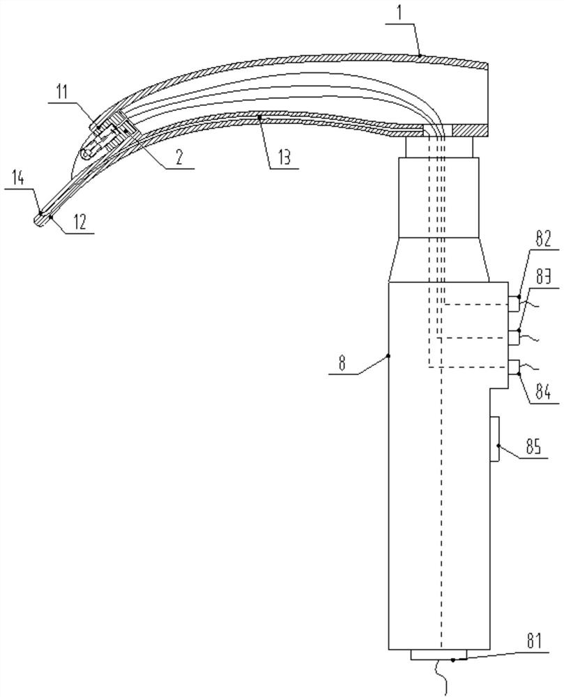
[0036] In the description of the present application, it should be understood that the orientations or positional relationships indicated by the terms "upper", "lower", "left", "right" etc. are based on the attached figure 1 The orientation or positional relationship shown, the orientation or positional relationship indicated by the term "front" is based on the attached figure 1 The "left" shown, the term "rear" indicates the orientation or positional relationship is based on the attached figure 1 The "right" shown is only for the ...


PUM


Abstract

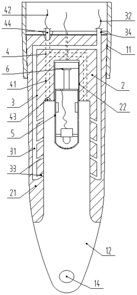
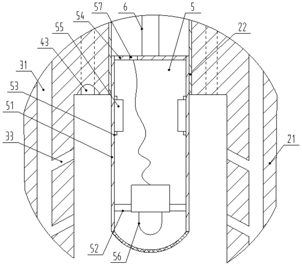
The invention discloses a multi-functional video laryngoscope. When in specific use, the telescoping of the video kit can be realized by controlling the driving mechanism, so as to meet the needs of different patients or different video exposure fields; when there is secretion blocking or covering When the visual kit affects the clear display of the exposed field of view, the flushing combination and the suction combination can be controlled. After the flushing liquid flushes the visual kit, it is taken away through the suction port, and then the visual kit can be quickly flushed and cleared. The secretion on the kit keeps the visual kit clear; in addition, after the liquid washes and the liquid on the body passes through, the heat generated by the visual kit can be taken away, and then the water cooling effect can be achieved, thus effectively solving the problem of possible Depending on the temperature influence of the kit, the clear display of the display is guaranteed, and it has the characteristics of simple structure, reasonable layout, multiple functions, safe and convenient use.

Description

technical field [0001] The invention relates to the technical field of medical instruments, in particular to a multifunctional video laryngoscope. Background technique [0002] Due to the deep position of the larynx and its complicated physiological structure, it cannot be directly seen. In medical examination of the larynx, a laryngoscope is often needed. Laryngoscopy can provide a detailed understanding of the abnormality of the laryngeal structure, clarify the location and scope of the lesion, and perform a biopsy of the lesion if necessary. With the development of modern medicine and technology, video laryngoscopes with monitors have been more widely used because they can show the local anatomy of the throat more clearly. The emergence of video laryngoscope has greatly reduced the probability of difficult glottis exposure, improved the success rate of tracheal intubation, reduced airway damage and mortality related to difficult airway, and demonstrated the impact of sci...

Claims


Application Information

Patent Timeline
Patent Type & Authority Patents(China)
IPC IPC(8): A61B1/267A61B1/015A61B1/04A61B1/12A61M16/04
CPCA61B1/00071A61B1/015A61B1/04A61B1/126A61B1/128A61B1/267A61M16/04
Inventor 张晓隆
Owner THE SECOND HOSPITAL AFFILIATED TO WENZHOU MEDICAL COLLEGE
Learn More