Synchronous solid-liquid separation crawler conveying structure for air excitation negative pressure system
A solid-liquid separation and crawler technology, which is applied in filtration separation, separation methods, moving filter element filters, etc., can solve the problems of uncontrollable speed and low conveying efficiency, and achieve the effects of smooth operation, high strength and low cost.
- Summary
- Abstract
- Description
- Claims
- Application Information
AI Technical Summary
Problems solved by technology
Method used
Image
Examples
Embodiment 1
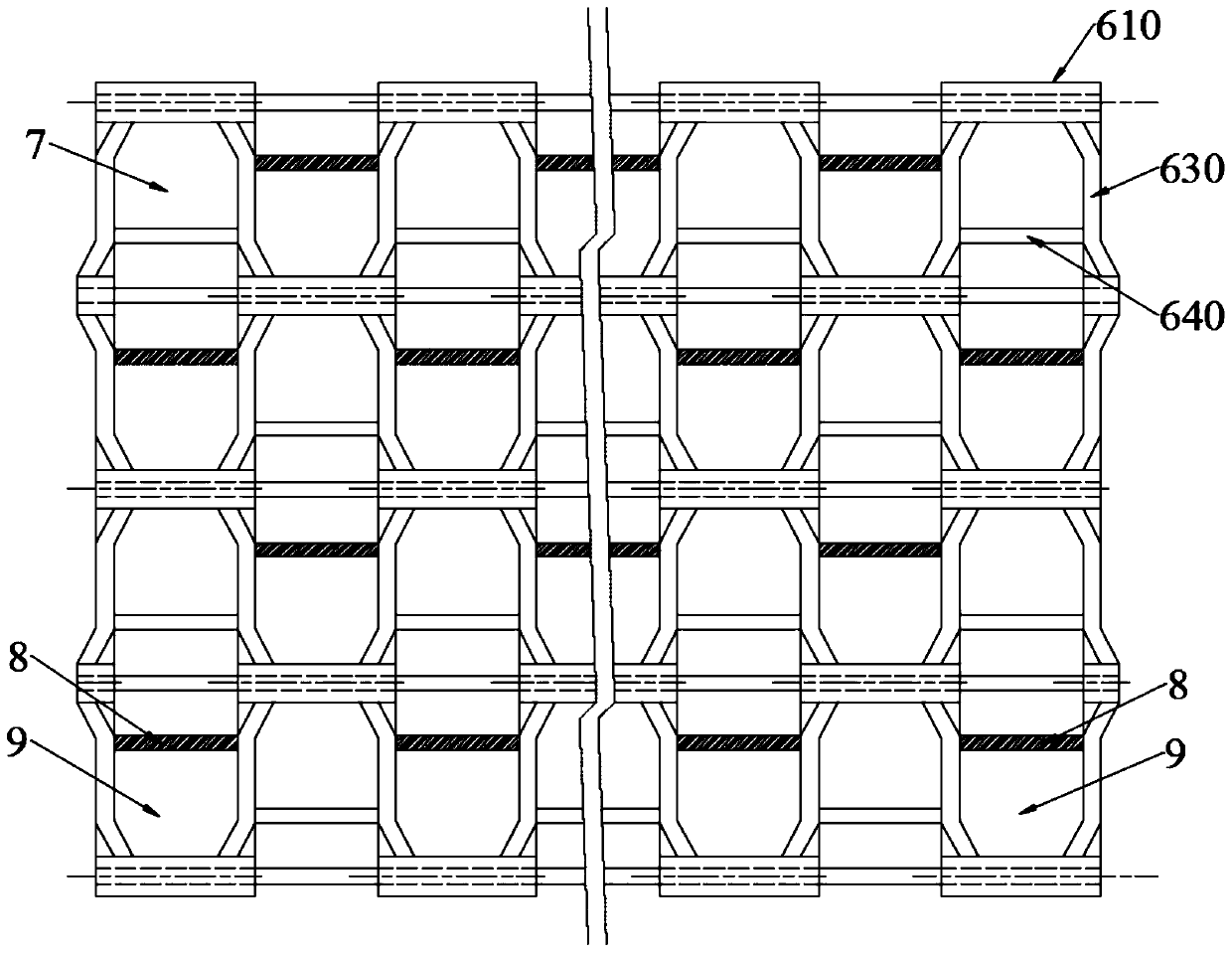
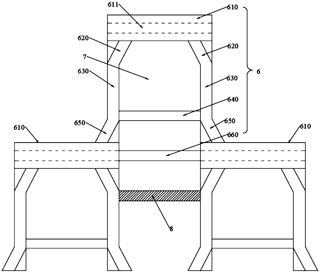
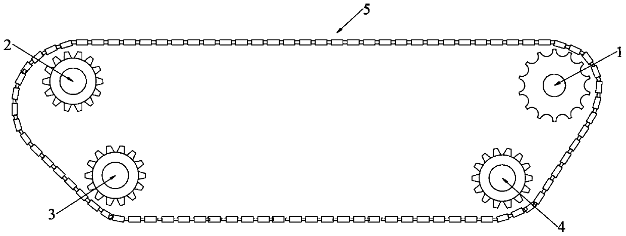
[0028] The synchronous solid-liquid separation track conveying structure used in the air excitation negative pressure system of the present invention includes a driving wheel 1, a first driven wheel 2, a second driven wheel 3, a tensioning wheel 4 and a track body 5; the track body 5 Several track units 6 are combined vertically and horizontally, and multiple track units 6 combined horizontally are connected end-to-end to form a ring. The track unit 6 includes pin shafts 610, side beams, first ribs 620, and second ribs 650. and connecting pin 660; the side walls at the left and right ends of the pin shaft 610 are all connected to one end of the side beam 630, and the other ends of the two side beams 630 are connected to each other with the two pin shafts 610 of the next single adjacent crawler unit 6 respectively. Each side beam 630 is perpendicular to the pin shaft 610, a reinforcing beam 640 is arranged between the two side beams 630, the number of the first reinforcing beam ...
Embodiment 2
[0031] This embodiment is further optimized on the basis of Embodiment 1 as follows: a plurality of driving wheels 1 are arranged side by side, the driving wheel 1 and the first driven wheel 2 are located on the same plane, and the second driven wheel 3 and the tensioning wheel 4 are located on the same plane. Below the line connecting the wheel 1 and the first driven wheel 2, the second driven wheel 3 is located at one end close to the first driven wheel 2, and the tensioning wheel 4 is located at one end close to the driving wheel 1.
[0032] After adopting the above-mentioned technical scheme, through the driving wheel 1, the first driven wheel 2, the second driven wheel 3 and the tensioning wheel 4, the stable operation of the track body 5 is realized, and the driving of the track body 5 is realized through the driving wheel 1, and the driving wheel 1 Connected with a servo motor, the speed can be adjusted according to the actual separation requirements.
Embodiment 3
[0034] The present embodiment is further optimized on the basis of Embodiment 1 as follows: connecting beams 8 are connected between adjacent side beams 630 of any horizontally adjacent crawler unit 6, connecting beams 8, side beams 630 at both ends of the connecting beam 8 A second positioning hole 9 having the same shape as the first positioning hole 7 is enclosed between the pin shaft 610 below the connecting beam 8 .
[0035]After adopting the above-mentioned technical scheme, the crawler body 5 is further reinforced through the function of the connecting beam 8, while ensuring the strength of the crawler body 5, the connecting beam 8, the side beams 630 at the left and right ends of the connecting beam 8 and the lower end of the connecting beam 8 The pin shaft 610 forms the second positioning hole 9, and the second positioning hole 9 and the first positioning hole 7 are actually identical, and are only distinguished for different descriptions. The crawler unit 6 only save...
PUM
 Abstract
Description
Claims
Application Information
 - R&D
- Intellectual Property
- Life Sciences
- Materials
- Tech Scout
- Unparalleled Data Quality
- Higher Quality Content
- 60% Fewer Hallucinations
Browse by: Latest US Patents, China's latest patents, Technical Efficacy Thesaurus, Application Domain, Technology Topic, Popular Technical Reports.
© 2025 PatSnap. All rights reserved.Legal|Privacy policy|Modern Slavery Act Transparency Statement|Sitemap|About US| Contact US: help@patsnap.com


