
Inner hole chamfering device

A technology of chamfering device and inner hole, used in positioning device, driving device, clamping and other directions, can solve the problems of low processing efficiency, inability to remove burrs with machine tools, and difficult to remove burrs, and achieve the effect of improving work efficiency

Pending Publication Date: 2019-09-10
合肥鼎聚精密制造有限责任公司
View PDF0 Cites 0 Cited by
  • Summary
  • Abstract
  • Description
  • Claims
  • Application Information

AI Technical Summary

Problems solved by technology

[0003] There are often burrs left on the inner wall of the workpiece processed by the equipment, and the burrs are generally difficult to remove. For example, when drilling a hole on a circular workpiece, burrs will be left on the inner diameter wall. The burrs cannot be removed by a machine tool, and only a hand-held wind pen and the like can be used to remove the burrs. Grinding small tools is labor-intensive and time-consuming, and grinding with a wind pen will make the shape uneven and concave; and when the existing equipment needs to chamfer the inner wall of the workpiece, it can only be chamfered by manual grinding. Angle, this processing method is time-consuming and laborious, and the processing efficiency is low

Method used


Image

  • Inner hole chamfering device
  • Inner hole chamfering device
  • Inner hole chamfering device

Examples


Embodiment Construction

[0026] The following will clearly and completely describe the technical solutions in the embodiments of the present invention with reference to the accompanying drawings in the embodiments of the present invention. Obviously, the described embodiments are only some, not all, embodiments of the present invention. Based on the embodiments of the present invention, all other embodiments obtained by persons of ordinary skill in the art without making creative efforts belong to the protection scope of the present invention.

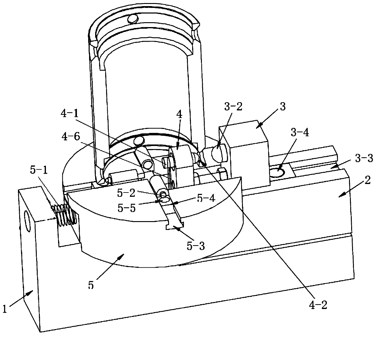
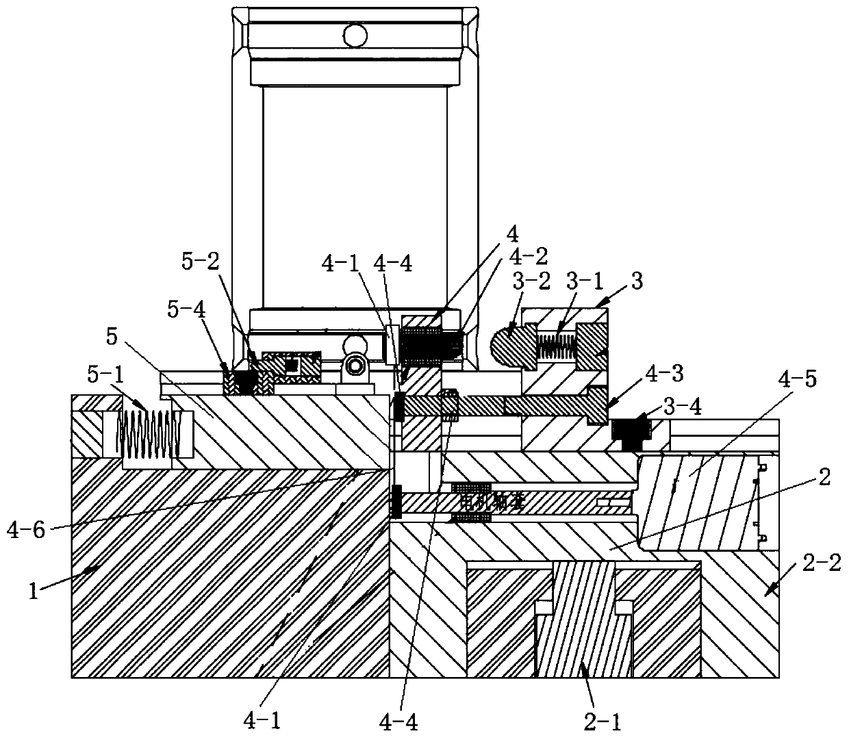
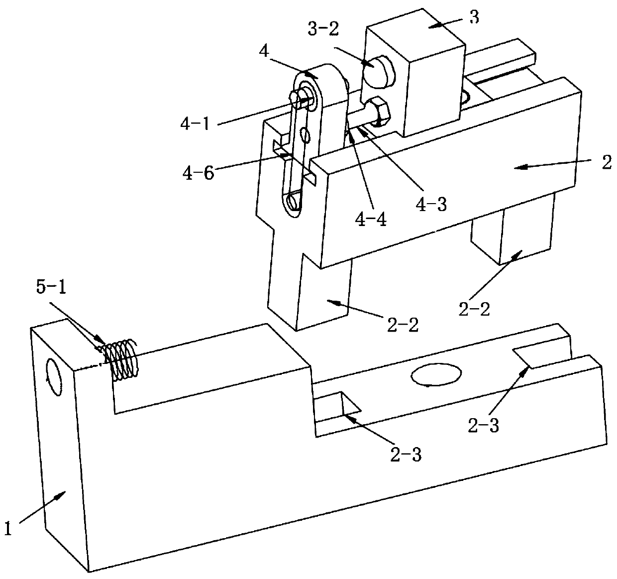
[0027] see Figure 1-3 , in an embodiment of the present invention, an inner hole chamfering device includes a base 1, a lifting assembly, a positioning assembly, a chamfering assembly and an operating panel 5;

[0028] The lifting assembly includes a lifting plate 2. The lower surface of the lifting plate 2 is fixedly connected with a guide block 2-2. Ejection mechanism;

[0029] The positioning assembly includes a positioning block 3, the positioning block...


PUM


Abstract

The invention discloses an inner hole chamfering device. The inner hole chamfering device comprises a base, a lifting assembly, a positioning assembly, a chamfering assembly and an operating panel, wherein the lifting assembly comprises a lifting plate; the lower surface of the lifting plate is fixedly connected to a guide block; the bottom end of the guide block is inserted on the base; an ejecting mechanism for ejecting the lifting plate is arranged on the base; the positioning assembly comprises a positioning block; the positioning block is movably connected to the lifting plate; a lockingcomponent for locking the positioning block is arranged on the lifting plate; the positioning block is elastically connected to a positioning ball; and the chamfering assembly comprises a mounting base and a chamfering cutter. The inner hole chamfering device facilitates the chamfering of the inner side wall of a manufacturing workpiece, and improves the work efficiency.

Description

technical field [0001] The invention relates to the technical field of inner hole chamfering equipment, in particular to an inner hole chamfering device. Background technique [0002] Chamfering refers to the processing of cutting the edges and corners of the workpiece into a certain slope. The chamfering is to remove the burrs on the parts due to machining, and also to facilitate the assembly of the parts. Generally, the chamfering is made at the end of the parts. [0003] There are often burrs left on the inner wall of the workpiece processed by the equipment, and the burrs are generally difficult to remove. For example, when drilling a hole on a circular workpiece, burrs will be left on the inner diameter wall. The burrs cannot be removed by a machine tool, and only a hand-held wind pen and the like can be used to remove the burrs. Grinding small tools is labor-intensive and time-consuming, and grinding with a wind pen will make the shape uneven and concave; and when the ...

Claims


Application Information

Patent Timeline
Patent Type & Authority Applications(China)
IPC IPC(8): B23D79/04B23Q3/18B23Q5/10B23Q1/25
CPCB23D79/04B23Q3/18B23Q5/10B23Q1/25
Inventor 罗永春俞登勇马永真李帅
Owner 合肥鼎聚精密制造有限责任公司
Features
  • Generate Ideas
  • Intellectual Property
  • Life Sciences
  • Materials
  • Tech Scout
  • Unparalleled Data Quality
  • Higher Quality Content
  • 60% Fewer Hallucinations
Learn More