Fluidized limestone conveying system

A limestone and conveying system technology, applied in the direction of conveyors, conveying bulk materials, transportation and packaging, etc., can solve the problems of reducing the service life of conveying pipelines, reducing efficiency, and slow conveying speed, so as to achieve rational use of energy and avoid Partial clogging of pipelines and the effect of increasing service life

Active Publication Date: 2019-09-10
ZHEJIANG GUTE PNEUMATIC MACHINERY
View PDF6 Cites 0 Cited by
  • Summary
  • Abstract
  • Description
  • Claims
  • Application Information

AI Technical Summary

Problems solved by technology

[0004] 1. Due to the many edges and corners of the limestone powder particles after grinding, the high hardness results in great wear and tear on the pipeline during the transportation process, which greatly reduces the service life of the transportation pipeline;
[0005] 2. Due to the strong degassing ability of limestone powder, the fluidity of limestone is poor, and the conveying rate is extremely slow, which reduces the conveying efficiency;
[0006] 3. The large difference in particle siz

Method used


Image

  • Fluidized limestone conveying system
  • Fluidized limestone conveying system
  • Fluidized limestone conveying system

Examples


Embodiment 1

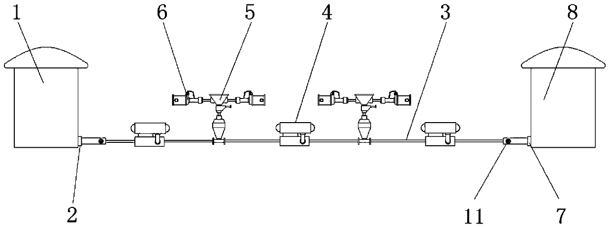
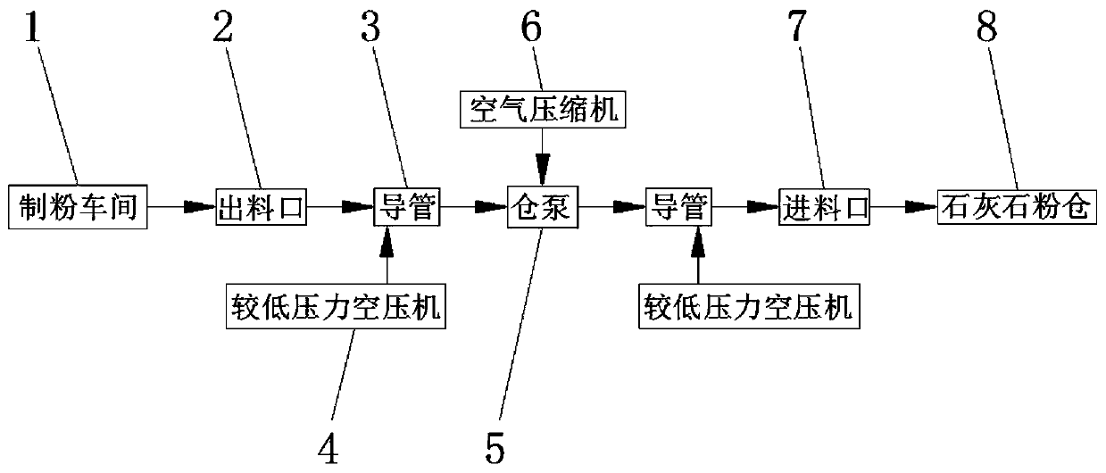
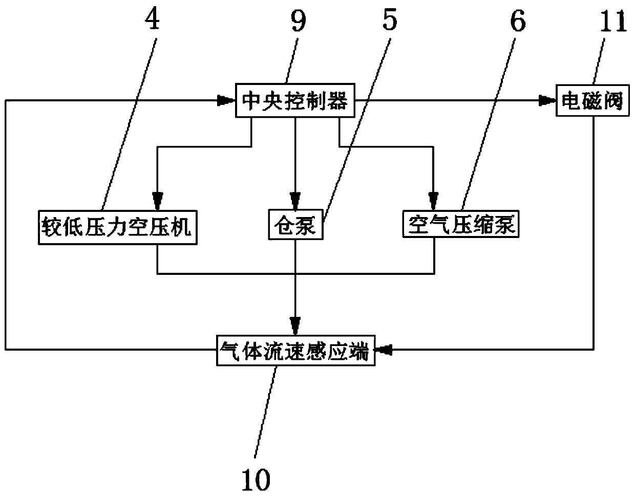
[0027] see Figure 1-3 , a fluidized limestone conveying system, comprising a discharge port 2 provided at the bottom of the milling workshop 1, a conduit 3 is provided on the inner thread of the discharge port 2, a warehouse pump 5 is installed at the other end of the conduit 3, and a warehouse pump 5 is installed on the other end of the conduit 3 The discharge port is connected with a limestone powder bin 8 through another conduit 3 , an air compressor 6 is installed at the vent on the top of the bin pump 5 , the end of the conduit 3 is connected with a lower pressure air compressor 4 , and the bottom of the limestone powder bin 8 There is a feed port 7, the inside of the feed port 7 is sealed with the end of the conduit 3, the input end of the warehouse pump 5 is electrically connected to the central processing unit 9, and the output end of the central processing unit 9 is connected to the lower pressure air compressor. The input ends of the air compressor 4 and the air com...

Embodiment 2

[0035] see Figure 1-3 , a fluidized limestone conveying system, comprising a discharge port 2 provided at the bottom of the milling workshop 1, a conduit 3 is provided on the inner thread of the discharge port 2, a warehouse pump 5 is installed at the other end of the conduit 3, and a warehouse pump 5 is installed on the other end of the conduit 3 The discharge port is connected with a limestone powder bin 8 through another conduit 3 , an air compressor 6 is installed at the vent on the top of the bin pump 5 , the end of the conduit 3 is connected with a lower pressure air compressor 4 , and the bottom of the limestone powder bin 8 There is a feed port 7, the inside of the feed port 7 is sealed with the end of the conduit 3, the input end of the warehouse pump 5 is electrically connected to the central processing unit 9, and the output end of the central processing unit 9 is connected to the lower pressure air compressor. The input ends of the air compressor 4 and the air com...

Embodiment 3

[0043] see Figure 1-3 , a fluidized limestone conveying system, comprising a discharge port 2 provided at the bottom of the milling workshop 1, a conduit 3 is provided on the inner thread of the discharge port 2, a warehouse pump 5 is installed at the other end of the conduit 3, and a warehouse pump 5 is installed on the other end of the conduit 3 The discharge port is connected with a limestone powder bin 8 through another conduit 3 , an air compressor 6 is installed at the vent on the top of the bin pump 5 , the end of the conduit 3 is connected with a lower pressure air compressor 4 , and the bottom of the limestone powder bin 8 There is a feed port 7, the inside of the feed port 7 is sealed with the end of the conduit 3, the input end of the warehouse pump 5 is electrically connected to the central processing unit 9, and the output end of the central processing unit 9 is connected to the lower pressure air compressor. The input ends of the air compressor 4 and the air com...


PUM


Abstract

The invention relates to the technical field of limestone conveying, and discloses a fluidized limestone conveying system. The fluidized limestone conveying system is characterized in that a discharging opening is formed in the bottom of a pulverizing workshop, a guide pipe is arranged in the discharging opening in a threaded mode, bin pumps are arranged at the other end of the guide pipe, the discharging openings of the bin pumps communicate with a limestone powder bin through the other guide pipe, air compressors are arranged at vent holes in the tops of the bin pumps, the ends of the guidepipe communicate with lower pressure air compressors, a feeding port is formed in the bottom of the limestone powder bin, and the output end of a central processing unit is electrically connected withthe input ends of the low-pressure air compressors and the input ends of the air compressors. According to the fluidized limestone conveying system, limestone particles are crushed to be smaller by arranging the lower pressure air compressors by utilizing the impact force of compressed gas, so that the abrasion between the limestone particles and the pipe wall is reduced, the service life of theguide pipes is prolonged, and meanwhile, the conveying system is suitable for conveying the limestone with various particle sizes.

Description

technical field [0001] The invention relates to the technical field of limestone transportation, in particular to a fluidized limestone transportation system. Background technique [0002] The desulfurization in the circulating fluidized bed boiler adopts the process of mixing limestone to meet the desulfurization index required by the national environmental protection. Generally, the independent limestone desulfurization system is selected, that is, the limestone feeding system is completely separated from the coal feeding system, and can be freely based on the emission of sulfur dioxide. value at any time to adjust the amount of limestone feed, so as to achieve the purpose of ensuring emissions and economical operation. [0003] At present, the fluidized limestone conveying system has the following disadvantages; [0004] 1. Due to the many edges and corners of the limestone powder particles after grinding, the high hardness results in great wear and tear on the pipeline ...

Claims


Application Information

Patent Timeline
IPC IPC(8): B65G53/06B65G53/58
CPCB65G53/06B65G53/58
Inventor 肖翰张寿根叶一舟萧亚兵
Owner ZHEJIANG GUTE PNEUMATIC MACHINERY
Why Eureka
Try Eureka