
Coating tooling and installation method for elongated reflectors

A mirror and strip-shaped technology, applied in the field of fixtures, can solve the problems of narrow installation environment of the coating cavity, and achieve the effect of eliminating the risk of bumping, reducing the tolerance size, and improving the control accuracy.

Active Publication Date: 2021-03-19
SHANGHAI MODERN ADVANCED ULTRA PRECISION MFG CENT
View PDF9 Cites 0 Cited by
  • Summary
  • Abstract
  • Description
  • Claims
  • Application Information

AI Technical Summary

Problems solved by technology

The general tooling design of the coating machine is to fix the supporting plate on the umbrella frame of the coating machine, and open the installation card slot suitable for the size of the mirror on the fixed supporting plate. After the mirror is cleaned, install the optical surface of the mirror to the tooling in the coating machine The installation environment of the fixture and the coating chamber is narrow, and it is easy to cause installation problems

Method used


Image

  • Coating tooling and installation method for elongated reflectors
  • Coating tooling and installation method for elongated reflectors
  • Coating tooling and installation method for elongated reflectors

Examples


Embodiment Construction

[0030] The present invention will be further described below in conjunction with the accompanying drawings.

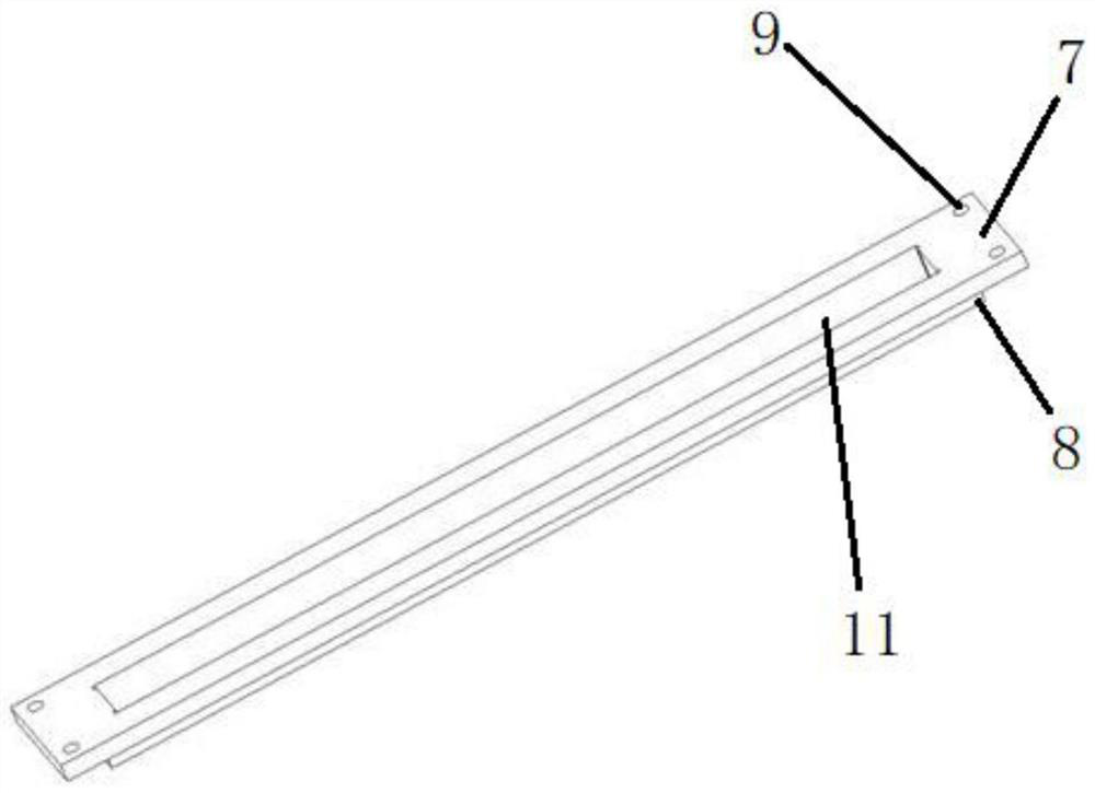
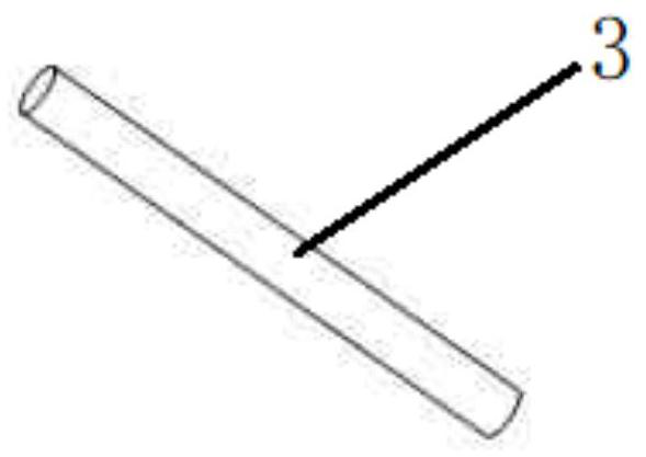
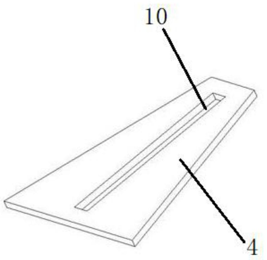
[0031] A kind of coating frock for elongated reflector, comprising a fixed supporting plate 4 such as image 3 As shown, two movable pallets 1, 2 are as figure 1 Shown and 4 positioning rods 3 as figure 2 shown. The fixed supporting plate 4 can be fixed on the umbrella stand of the coating machine, and a first rectangular groove 10 is opened in the center. The movable pallets 1 and 2 include a panel 7 and a bottom plate 8 that are bonded together up and down. The bottom plate 8 is equal in width, length and height to the first rectangular groove 10 , and can be embedded in the first rectangular groove 10 . The center of the movable pallet 1 and 2 is provided with a second rectangular groove 11, the second rectangular groove 11 is equal in width and length to the strip reflector, and the height of the strip reflector is greater than twice the second rectangular gro...


PUM

PropertyMeasurementUnit
lengthaaaaaaaaaa
sizeaaaaaaaaaa

Abstract

The invention relates to a film coating tool for a rectangular reflecting mirror and a mounting method. The film coating tool for the rectangular reflecting mirror comprises movable supporting plates,fixed supporting plates and positioning rods for mounting, wherein the movable supporting plates are provided with mounting positioning holes and are in direct contact with an optical surface of therectangular mirror; the rectangular mirror is fixed into clamping grooves of the movable supporting plates; the fixed supporting plates are fixed to an umbrella frame of a film coating machine; the movable supporting plates are fixed into clamping grooves of the fixed supporting plates; four positioning rods are used for accurately aligning the upper and lower movable supporting plates during mounting through the rectangular reflecting mirror tool, and thus the movable supporting plates are clung to the optical surface of the rectangular reflecting mirror. The film coating tool for the rectangular reflecting mirror has the beneficial effects that the positioning rods are similarly used for mounting guide rails, so that the risk of collision to side corners of the optical surface of the rectangular mirror in tool mounting process is basically removed; and meanwhile, preset tolerance size for tool design is extremely reduced, so that the control accuracy of clear aperature.

Description

technical field [0001] The invention relates to a mirror coating tooling, in particular to a fixture and an installation method designed and used for evaporating coating on some optical strip mirrors with a length exceeding 400 mm. Background technique [0002] In the process of the evaporation coating machine, because the coating principle requires that the optical coating surface "face down" the coating method is adopted, so the installation of the mirror coating tooling generally requires the optical surface to be in contact with the tooling, which leads to the optical surface and the mirror edge. There are different degrees of risk of contact damage in each corner. [0003] Among them, the long mirrors have more sides and corners, and the longer the size, the higher the operational risk. The long mirrors involved here generally refer to sizes above 400mm in length. The general tooling design of the coating machine is to fix the supporting plate on the umbrella frame of ...

Claims


Application Information

Patent Timeline
Patent Type & Authority Patents(China)
IPC IPC(8): C23C14/50C23C14/24
CPCC23C14/24C23C14/50
Inventor 莫海亮
Owner SHANGHAI MODERN ADVANCED ULTRA PRECISION MFG CENT
Learn More