Coating tool for large square reflecting lens

A reflective mirror surface and tooling technology, applied in sputtering plating, ion implantation plating, vacuum evaporation plating, etc., can solve the problems of difficult coating on the side of reflective mirrors, and achieve space-saving layout, high versatility, and convenience The effect of the design

Pending Publication Date: 2020-05-08
SHANGHAI MODERN ADVANCED ULTRA PRECISION MFG CENT
View PDF6 Cites 1 Cited by
  • Summary
  • Abstract
  • Description
  • Claims
  • Application Information

AI Technical Summary

Problems solved by technology

[0004] The purpose of the invention is to overcome the deficiencies of the prior art and solve the problem of difficult side coating of large square optical mirrors

Method used


Image

  • Coating tool for large square reflecting lens
  • Coating tool for large square reflecting lens
  • Coating tool for large square reflecting lens

Examples


Embodiment Construction

[0039] The present invention will be further described below in conjunction with the accompanying drawings and specific embodiments.

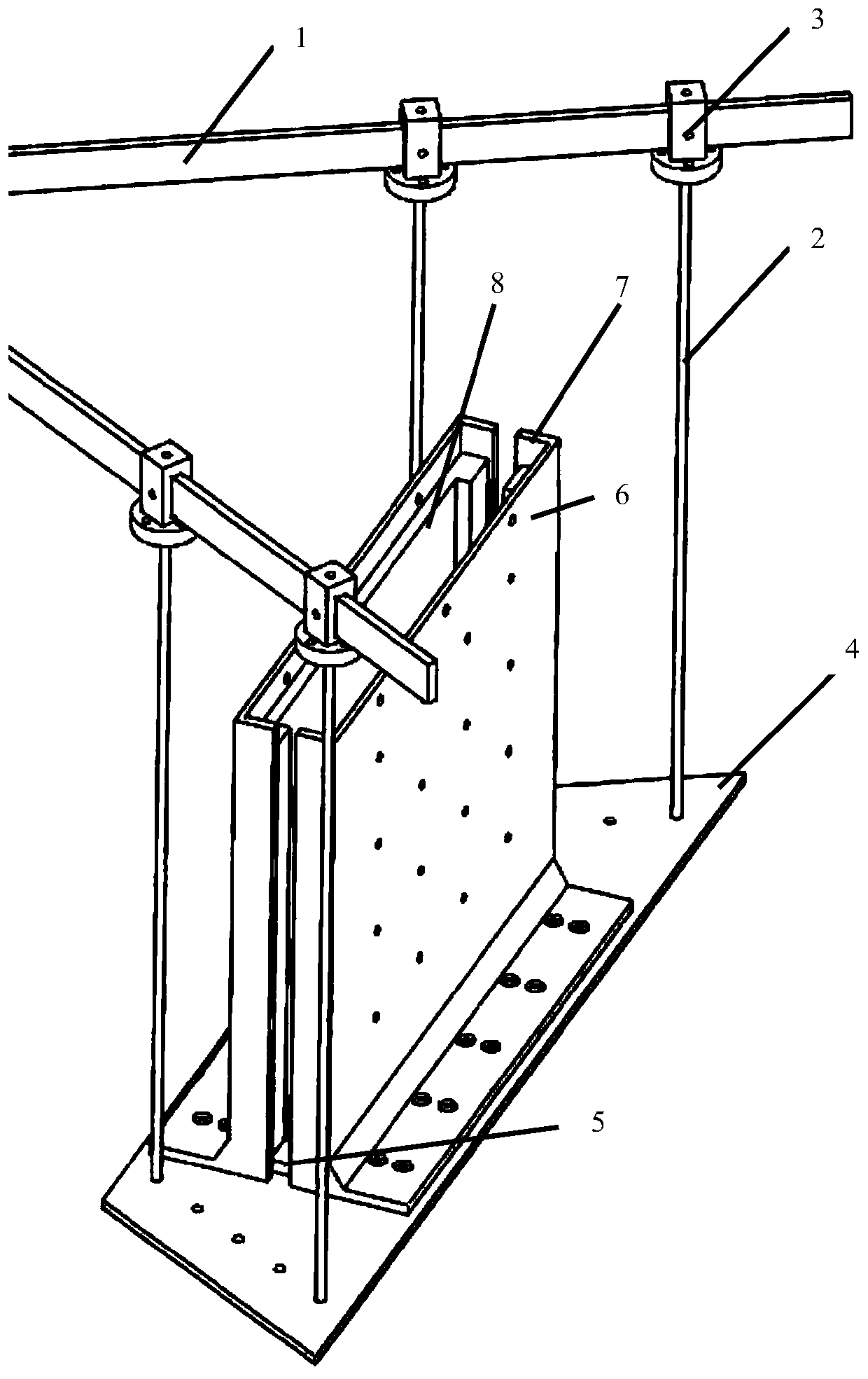
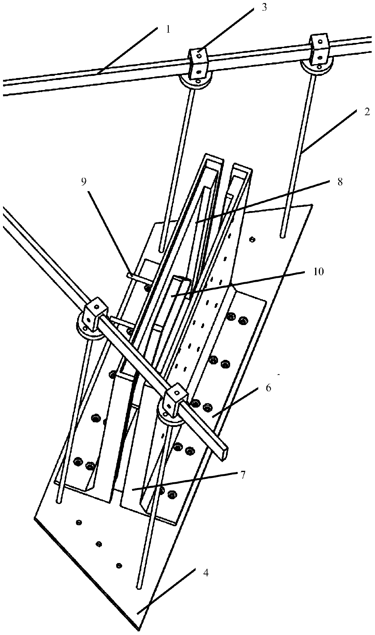
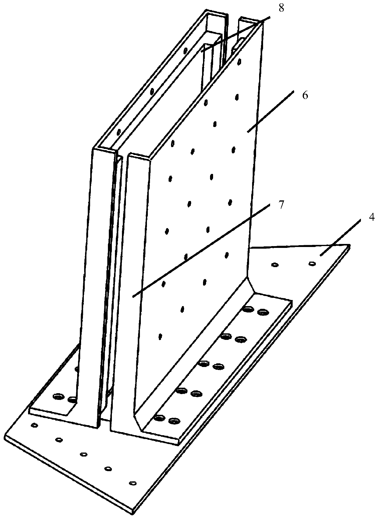
[0040] according to Figure 1 to Figure 6 The side coating tooling of a large reflective mirror as shown includes a locking block 3 fixed on the coating umbrella stand beam 1, and the bottom of the locking block 3 is suspended from a flat bottom plate 4 by a suspender 2, and the bottom plate 4 There is a strip-shaped coating steam hole in the center, and vertical baffles 6 are respectively fixed on both sides of the coating steam hole on the bottom plate 4; Break away from the rib 7 of relative space. The baffle 6 is L-shaped, and the lower transverse part of the baffle 6 is arranged in a direction away from the coating steam hole. Holes are distributed on the bottom plate 4, threaded holes are distributed on the lower transverse part of the baffle plate 6, and the bottom plate 4 and the baffle plate 6 are fixed by passing bolts through the h...


PUM


Abstract

The invention relates to a coating tool for a large square reflecting lens. The coating tool comprises a locking block fixed to a coating umbrella rack beam. A horizontally placed bottom plate is suspended at the bottom of the locking block through a suspender, a stripe-type coating steam through hole is formed in the center of the bottom plate, and vertical baffle plates are separately fixed to two sides of the coating steam through hole in the bottom plate; and retaining sides for preventing a to-be-coated workpiece from being separated out of a related space are also arranged on the side edges of the baffle plates in a protruding manner. The coating tool has the beneficial effects that side coating of the large square optical reflecting lens workpiece is positioned, and the coating toolis high in universality and does not harm the workpiece.

Description

technical field [0001] The invention relates to a tooling for evaporative coating on the side of a large square optical reflective lens whose external dimensions exceed 400mm*400mm*50mm. Background technique [0002] In the process of the evaporation coating machine, due to the requirements of the coating principle, the coating method of "facing down" the optical coating surface is generally adopted, and the lens needs to be continuously rotated during the coating process, so the coating tooling installation of the lens generally requires the optical surface and The contact of the tooling or the direct suspension of the optical surface makes it very difficult to fix the lens and control the optical aperture. Among them, the large square optical reflective lens has a large size, many corners, and a high standing height of the side coated lens, which leads to high operational risks. The large square optical reflective lenses involved here generally refer to dimensions above 4...

Claims


Application Information

Patent Timeline
Patent Type & Authority Applications(China)
IPC IPC(8): C23C14/24C23C14/50
CPCC23C14/24C23C14/50
Inventor 徐松汪明天张辉尤磊陆奕玮莫海亮
Owner SHANGHAI MODERN ADVANCED ULTRA PRECISION MFG CENT
Why Eureka
Try Eureka