Wall plastering machine capable of assisting in travelling

A technology for assisting walking and wall plastering, which can be used in construction, building construction, etc., and can solve the problems of high labor intensity, cumbersome operation methods, and low plastering efficiency.

Pending Publication Date: 2019-09-10
FOSHAN TUPO MACHINERY MFG CO LTD
View PDF0 Cites 1 Cited by
  • Summary
  • Abstract
  • Description
  • Claims
  • Application Information

AI Technical Summary

Problems solved by technology

After the wall plastering machine performs a plastering process, the worker manually pushes the body to rotate the universal walking wheel on the bottom frame, and then moves the whole wall

Method used


Image

  • Wall plastering machine capable of assisting in travelling
  • Wall plastering machine capable of assisting in travelling
  • Wall plastering machine capable of assisting in travelling

Examples


Embodiment 1

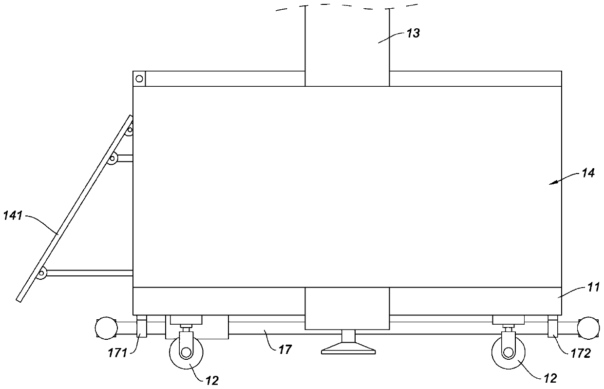
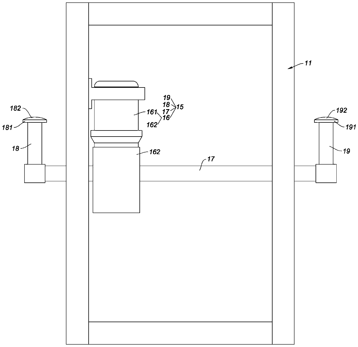
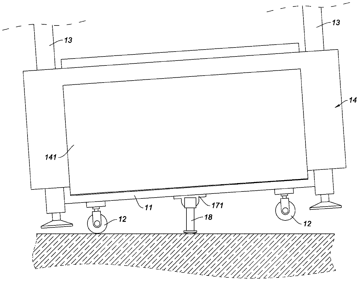
[0032] Such as figure 1 , figure 2 , image 3As shown, the present embodiment is a wall plastering machine that can assist walking, including a chassis 11, an upright rail 13 and a plastering main frame 14, the upright rail 13 is installed on the bottom frame 11, and the plastering main frame 14 is installed on an upright on the track 13, and the plastering host 14 can move up and down along the upright track 13; universal traveling wheels 12 are also installed on the underframe 11, specifically the four bottom corners of the underframe 11 are equipped with universal traveling wheels In order to realize the purpose of the wall plastering machine that can assist walking, the wall plastering machine that can assist walking also includes an auxiliary walking mechanism 15, and the auxiliary walking mechanism 15 includes a power unit 16, a rotating shaft 17, and a first floor support rod 18 and the second ground support rod 19; the rotating shaft 17 is rotatably installed on the...

Embodiment 2

[0038] The difference between this embodiment and embodiment 1 is: as Figure 4 As shown, in this embodiment, two first ground support rods 22, 23 are installed at one end of the rotating shaft 21, and the two first ground support rods 22, 23 are evenly arranged around the axis of the rotating shaft 21. The first ground support rods 22, 23 are fixed on the rotating shaft 21; at the other end of the rotating shaft 21, 2 second ground support rods 24, 25 are installed, and the 2 second ground support rods 24, 25 also wrap around The shaft centers of the rotating shaft 21 are evenly arranged, and the two second ground support rods 24, 25 are also fixed on the rotating shaft 21. Such a design makes the wall plastering machine, which can assist in walking, faster when walking, which is conducive to improving work efficiency.

Embodiment 3

[0040] The difference between this embodiment and embodiment 1 is: as Figure 5 , Figure 6 As shown, one end of the rotating shaft 31 is provided with a first hub 311, and the other end of the rotating shaft 31 is provided with a second hub 314; the first ground support rod 32 is installed on the first hub 311, and the first support ground The rod 32 can be telescopically moved relative to the first hub 311. The structure of the first floor support rod 32 that can be telescopically moved relative to the first hub 311 is generally formed in the first hub 311 with a first movable cavity 312. A limiting ring portion 313 is formed on the edge of the opening of the first movable chamber 312, and one end of the first floor support rod 32 is inserted into the first movable chamber 312, and when the first floor support rod 32 is inserted into the first movable chamber 312 That end is formed with a big head 322 that is spaced with the limit ring portion 313, so that the first floor s...


PUM


Abstract

The invention relates to a wall plastering machine capable of assisting in travelling. The wall plastering machine comprises a bottom frame, a vertical rail and a plastering main machine, and furthercomprises an auxiliary travelling mechanism; the vertical rail is mounted on the bottom frame, and the plastering main machine is mounted on the vertical rail; universal travelling wheels are furthermounted on the bottom frame; the auxiliary travelling mechanism comprises a power device, a rotating shaft, one or more first grounding rods and one or more second grounding rods; the rotating shaft is rotatably mounted on the bottom frame, and the power device is used for driving the rotating shaft to rotate; the first grounding rods are mounted at one end of the rotating shaft, and the second grounding rods are mounted at the other end of the rotating shaft; grounding ends are arranged on the first grounding rods and the second grounding rods correspondingly, and the grounding ends of the first grounding rods and the grounding ends of second grounding rods are arranged in the mode of simultaneously landing and lifting off. The wall plastering machine has the characteristics that the labor intensity of workers can be relieved, the wall plastering machine is overall moved to a next plastering station easily and quickly, then the plastering efficiency is improved, and benefits are increased advantageously.

Description

technical field [0001] The invention relates to the technical field of construction equipment, in particular to a wall plastering machine capable of assisting walking. Background technique [0002] At present, the wall plastering machine used in construction is mainly composed of two parts, the chassis and the body. The universal walking wheel is installed on the chassis, the body is installed on the chassis, and the ash hopper and the plastering board are installed on the frame. There is a certain included angle with the body, the slurry flows from the ash hopper to the wiper board, and then the body moves up along the vertical track installed on the bottom frame, and then the slurry is applied to the wall through the wiper board. After the wall plastering machine performs a plastering process, the worker manually pushes the body to rotate the universal walking wheel on the bottom frame, and then moves the whole wall plastering machine to the next plastering station for pla...

Claims


Application Information

Patent Timeline
IPC IPC(8): E04F21/08
CPCE04F21/08
Inventor 王建虎
Owner FOSHAN TUPO MACHINERY MFG CO LTD
Why Eureka
Try Eureka