Online monitoring method and system of air valve

A technology for air valves and maintenance valves, which is applied in the direction of valve operation/release devices, valve details, valve devices, etc. It can solve the problems of low reliability, inability to be timely and effective, and close the water inlet of air valves to achieve intelligent, Avoid the effects of water hammer in the pipe network

Pending Publication Date: 2019-09-10
WUHAN DAYU VALVE
View PDF5 Cites 2 Cited by
  • Summary
  • Abstract
  • Description
  • Claims
  • Application Information

AI Technical Summary

Problems solved by technology

[0004] Regardless of the structure of the air valve, it is necessary to rely on manual reading inspections in the operating state; this monitoring method is inefficient and low in reliability; it is time-consuming and laborious, and lacks system data traceability or prediction
CN 109237120 A discloses an air valve state monitoring device and method, but the method is only for periodic monitoring, and only an alarm signal is generated after abnormality is detected, and management personnel are notified to go to the site for maintenance and repair, and the air valve cannot be monitored online at all. Remote operation control, it is impossible to timely and effectively control the air valve according to the monitoring status
Moreover, the trigger module is only a micro switch / pressure sensor / noise sensor, but a single trigger module cannot accurately judge the state of the valve. For example, when the valve leaks and the valve is exhausted, the micro switch will open and send an action signal, which cannot be detected when the air valve leaks. Instantaneously close the water inlet of the air valve, causing serious accidents such as water hammer in the pipe network, pipe burst and pipe collapse

Method used


Image

  • Online monitoring method and system of air valve
  • Online monitoring method and system of air valve
  • Online monitoring method and system of air valve

Examples


Embodiment Construction

[0035] The following specific examples illustrate the present invention in further detail.

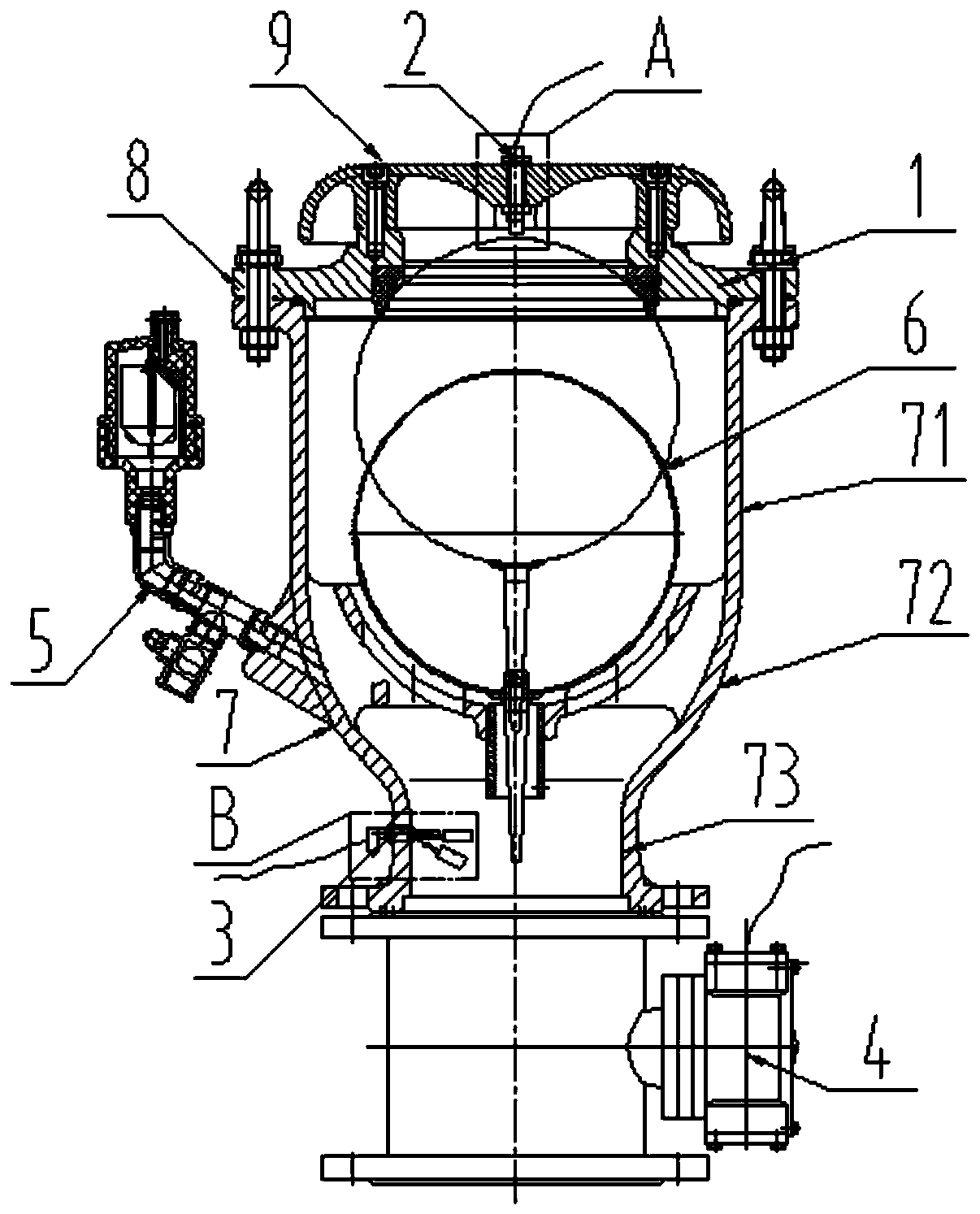
[0036] Such as Figure 1-2 As shown, the present invention provides a monitoring method for an air valve, the steps are:

[0037] a. Set the electric maintenance valve 4 at the water inlet of the air valve 1, and open it under normal conditions;

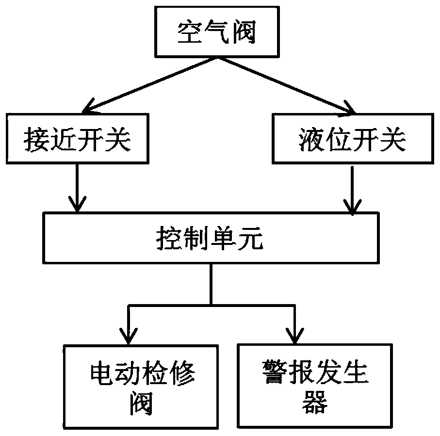
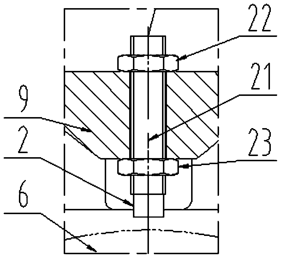
[0038] Proximity switch 2 is set on the top of air valve 1. Use proximity switch 2 to monitor the float position in real time. Proximity switch 2 is located where the float is sealed with the large exhaust port (here is the highest position that the float can reach in the valve) Signal A is sent when it is lower than the seal with the large exhaust port, and signal B is sent;

[0039] The air valve 1 or the electric maintenance valve 4 is equipped with a liquid level switch 3, the liquid level switch 3 is a magnetic floating liquid level sensor, and the liquid level switch 3 is used to monitor the water level in the air valve 1 in real time...


PUM


Abstract

The invention discloses an online monitoring method and system of an air valve. The method comprises the following steps: a, arranging an electric service valve at a water inlet of the air valve; monitoring the position of a floating ball of the air valve and the water level state in real time; and sending the acquired data to a control unit; b, determining the normal work state and fault state ofthe air valve through the control unit based on the acquired data; and ca, immediately sending a signal to the electric service valve to close the valve through the control unit; and alarming. According to the method, signals sent by a proximity switch and a liquid level switch are utilized to accurately determine various working states of the air valve; the control unit immediately controls theelectric service valve to be closed in case of trace air exhausting fault state and water leaking fault state of a seal of a big air exhausting port; an alarm is controlled to alarm, so that malignantaccidents such as pipe net knocking, pipe exploding and pipe collapsing can be avoided, and as a result, an intelligent valve is realized.

Description

technical field [0001] The invention relates to the technical field of valves, in particular to an online monitoring method and system for air valves. Background technique [0002] The composite intake and exhaust valve (referred to as the air valve) has the functions of automatic exhaust, micro exhaust, and automatic air supply on the one hand, improving the discharge efficiency of the water pipeline; on the other hand, when negative pressure is generated in the pipeline, it can quickly suck in Air, protect the pipeline from negative pressure damage. Air valves are widely used in various water delivery pipelines, which play a role in safety protection, energy saving and consumption reduction for pipelines. They are key equipment on water delivery pipelines. Problems such as air resistance, pipe burst, negative pressure and even equipment damage caused by water hammer seriously affect the normal water supply, reduce the efficiency of water supply, and even completely paraly...

Claims


Application Information

Patent Timeline
Patent Type & Authority Applications(China)
IPC IPC(8): F16K37/00F16K31/02
CPCF16K31/02F16K37/0091
Inventor 李习洪詹小华张梅华
Owner WUHAN DAYU VALVE
Why Eureka
Try Eureka