
Ejector tube and stove ejector with ejector tube

A technology of ejector tube and ejector, which is applied to burners, household appliances, household stoves/stoves, etc., can solve problems such as poor air ejection ability

Active Publication Date: 2019-09-10
NINGBO FOTILE KITCHEN WARE CO LTD
View PDF5 Cites 0 Cited by
  • Summary
  • Abstract
  • Description
  • Claims
  • Application Information

AI Technical Summary

Problems solved by technology

[0004] The technical problem to be solved by the present invention is to provide an ejector tube and a cooker ejector containing it in order to overcome the defect that the ejector tube in the prior art has poor ejection ability to air

Method used


Image

  • Ejector tube and stove ejector with ejector tube
  • Ejector tube and stove ejector with ejector tube
  • Ejector tube and stove ejector with ejector tube

Examples


Embodiment 1

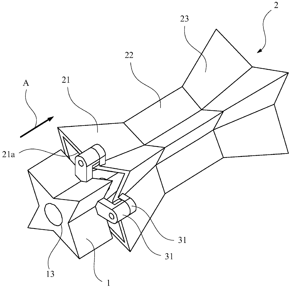
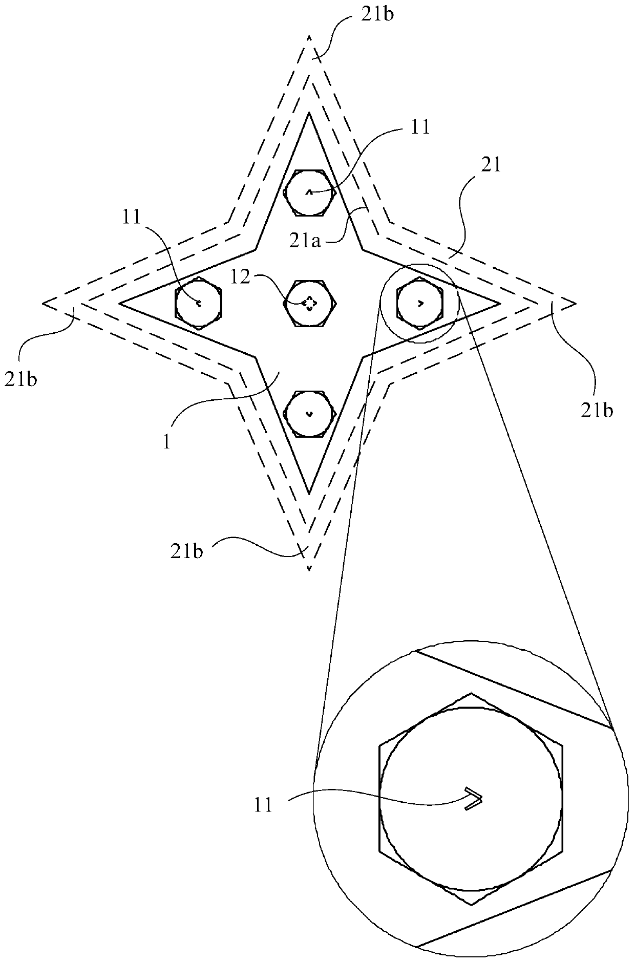
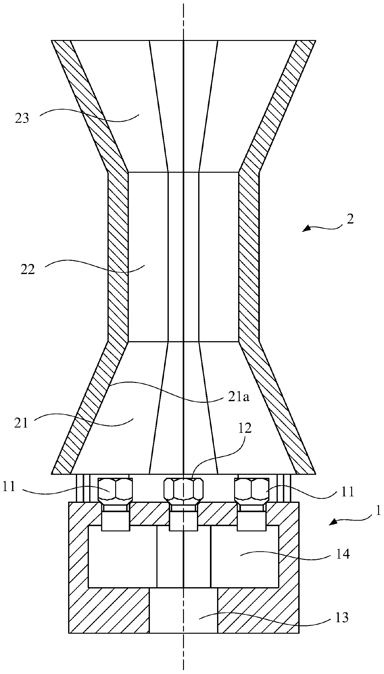
[0043] like figure 1 and figure 2 As shown, the present invention provides a cooker ejector, which includes a nozzle 1 and an ejector pipe 2 sequentially arranged along the airflow direction A. Among them, the direction of the radiation tube 2 can be divided into three parts: contraction section 21, horizontal section 22, and expansion section 23 according to the changes in the cross section of the gas flow. Set up towards the entrance of the contraction section 21, and these first exit 11 along the edge of the inner cavity 21A of the inner cavity 21 of the shrinkage section 21 in order to set the inner cavity settings around the contraction section 21 (please refer to the details (see the details, see figure 2 ). Through this structure settings, the gas sprayed from the first exit 11 can directly act on the inner wall of the contraction section 21, which improves the air flow rate of the inner wall surface of the contraction section 21, so that the inner wall surface shou...

Embodiment 2

[0053] This embodiment provides a cooker ejector, the structure of which is substantially the same as that provided in Embodiment 1. The difference is that, in this embodiment, the injection tube 2 only includes the constricted section 21 and the horizontal section 22 , but does not include the expanded section 23 . like Figure 4 As shown, the end of the horizontal section 22 along the airflow direction A is closed, and a number of openings are provided on the side wall of the horizontal section 22, so that the mixed gas in the injection pipe 2 can communicate with the external stove fire cover. Wherein, these openings are arranged on the side wall surface of the horizontal section 22 around along the inner cavity section of the horizontal section 22 .

[0054] Since the horizontal section 22 in the present embodiment is also a polygonal structure, there is a corresponding relationship between the apertures of these holes and the straight-line distance between the holes and ...


PUM


Abstract

The invention discloses an ejector tube and a stove ejector with the ejector tube. The ejector tube is provided with a contraction section, and the section shape of the inner cavity of the contractionsection is polygonal. Compared with a traditional round, oval or other circular arc-shaped ejector tube, the polygon has more the inner wall perimeter under the condition that the same cross-sectional area is occupied, the structure can be used for effectively improving the inner wall area of the ejector tube under the condition that the section of the pipeline is the same, and thus more air canbe sucked under the condition that the pressure of the surface of the inner wall is the same, and the ejection effect of the ejector tube on air is improved.

Description

technical field [0001] The invention involves a burner field, which specializes in a spinning tube and a stove -containing spinator. Background technique [0002] The biography is one of the important components of the cooker. It receives the gas from the nozzle to use the gas flow to reflect the air in the surrounding environment. The cross-sectional shape of the injection pipe is usually circular or elliptical, and it can be divided into a constricted section, a horizontal section and an expanded section according to the change of the cross-section along the gas flow direction. [0003] Among them, the existing radiation tube's ability to radiate air is not good, which directly affects the combustion effect of the cooker. Therefore, how to improve the radiation capacity of the radiation tube has become the research and development designer's research focus. Contents of the invention [0004] The technical problem to be solved by the present invention is to provide an e...

Claims


Application Information

Patent Timeline
IPC IPC(8): F23D14/64F23D14/04F24C3/08
CPCF23D14/04F23D14/64F24C3/085
Inventor 程永超郑军妹
Owner NINGBO FOTILE KITCHEN WARE CO LTD
Learn More