A construction device and construction method for road vibration and noise reduction

A technology of vibration reduction and noise reduction, construction device, applied in road safety devices, roads, roads, etc., can solve the problems of high noise, high energy loss, low effective work rate, etc., to reduce vibration noise, reduce vibration loss, The effect of reducing vibration loss

Active Publication Date: 2020-03-06
马超祥
View PDF6 Cites 3 Cited by
  • Summary
  • Abstract
  • Description
  • Claims
  • Application Information

AI Technical Summary

Problems solved by technology

[0006] Aiming at the problems of excessive energy loss, low effective work rate, and high noise caused by excessive vibration when railings are fixed in the prior art, the present invention provides a construction device and construction method for road vibration and noise reduction; Before the impact device hits the railing, part of the kinetic energy formed by the impact device is transferred to the railing, so that the railing has an initial kinetic energy. The impact device and the railing gradually approach until the impact device touches the top of the railing. The impact device continues to push the railing to move synchronously, and the impact device automatically The kinetic energy generated from top to bottom begins to be completely transferred to the railing, and then the bottom of the railing is inserted into the soil. During this process, the vibration loss caused by the impact device on the top of the railing is reduced, the effective work rate is improved, and the vibration noise

Method used


Image

  • A construction device and construction method for road vibration and noise reduction
  • A construction device and construction method for road vibration and noise reduction
  • A construction device and construction method for road vibration and noise reduction

Examples


Embodiment 1

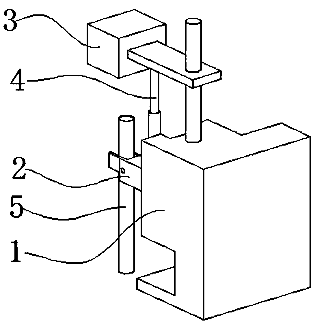
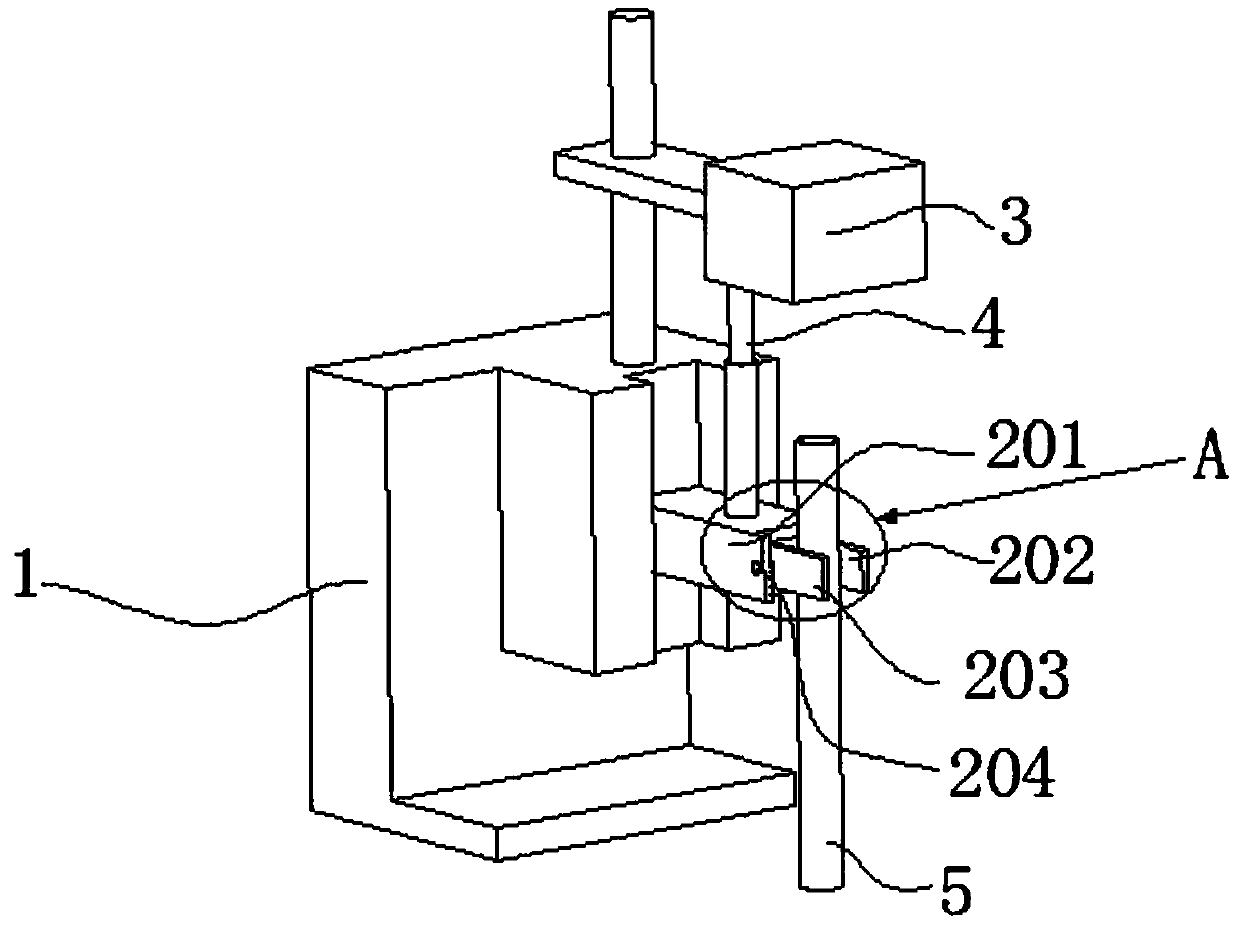
[0043] Such as figure 1 , figure 2 As shown, a road vibration and noise reduction construction device is used to install a railing 5; it includes a support base 1, a clamping device 2, an impact device 3 and a pre-transmission device 4, and one end of the clamping device 2 slides It is connected to the support base 1 and can move along the vertical space, and the other end is used to clamp the railing 5; the impact device 3 is connected to the support base 1; the impact device 3 is located on the clamping device 2 Above; the impact device 3 moves from top to bottom to form kinetic energy and then give the railing 5 a tendency to move downward; the pre-transmission device 4 is used to form a part of the impact device 3 before the impact device 3 contacts the railing 5 The kinetic energy is transferred to the railing 5.

[0044] Specifically, such as Figure 5 As shown, the clamping device 2 includes a mechanical arm 201, a left splint 202 and a right splint 203; one end of ...

Embodiment 2

[0050] With embodiment 1, difference is: as Figure 4 As shown, the pre-transmission device 4 includes a sleeve 405, a connecting rod 406 and a spring 407; the bottom of the sleeve 405 is connected to the mechanical arm 201 or the clamping device 2; the bottom of the connecting rod 406 is inserted In the sleeve 405 , the top is connected with the impact device 3 ; one end of the spring 407 is connected with the sleeve 405 or the mechanical arm 201 , and the other end is connected with the bottom of the connecting rod 406 .

[0051] In this embodiment, the connecting rod moves downward under the action of the impact device, the spring enters the compressed state from the stretched state, and gives the sleeve a thrust to move downward, and the clamping device moves downward, driving the railing to move downward, and the impact device Part of the kinetic energy generated from top to bottom is transmitted to the railing, so that the railing has a certain initial descending velocit...

Embodiment 3

[0053] A kind of construction method, use the construction device of road vibration reduction and noise reduction described in embodiment 1, the following content is its specific description:

[0054] A kind of construction method, its concrete steps are:

[0055] a. Put the railing 5 between the left clamping plate 202 and the right clamping plate 203, rotate the two-way threaded column 204, the left clamping plate 202 and the right clamping plate 203 move close to each other and clamp the railing 5 tightly;

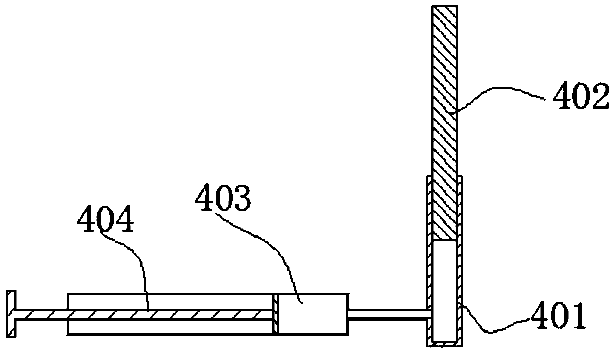
[0056] b. The impact device 3 moves from top to bottom. Before contacting the top of the railing 5, the impact device 3 moves from top to bottom, and the hydraulic rod 402 moves downward, pushing the hydraulic oil in the hydraulic cylinder 401 to flow into the auxiliary cylinder 403, giving hydraulic pressure The thrust of the cylinder 401 moving downward, the clamping device 2 moves downward, drives the railing 5 to move downward, and part of the kinetic energy generat...


PUM


Abstract

The invention discloses a highway vibration and noise reduction construction device and a construction method thereof, and belongs to the technical field of highway railing construction; the highway vibration and noise reduction construction device comprises a supporting seat, a clamping device, an impact device and a pre-transmission device; one end of the clamping device is slidably connected tothe supporting seat and can move along a vertical space, and the other end of the clamping device is used for clamping a railing; the impact device is connected to the supporting seat; the impact device is positioned above the clamping device; the impact device moves from top to bottom to form kinetic energy so as to give a downward movement trend to the railing; according to the invention, a part of kinetic energy formed by the impact device can be transmitted to the railing, so the railing has an initial kinetic energy; the impact device and the railing gradually approach until the impact device is in contact with the top of the railing, the impact device continues to push the railing to move synchronously, so the kinetic energy generated by the impact device from top to bottom starts to be completely transferred to the railing, and then the bottom of the railing is inserted into soil.

Description

technical field [0001] The invention belongs to the technical field of road railing construction, and in particular relates to a construction device and a construction method for road vibration and noise reduction. Background technique [0002] Highway fence network is the most important transportation infrastructure, especially the expressway developed in the 1980s. It plays an important role in the development of national economy and society. Highway fence network is an important maintenance and safety guarantee facility for expressways. [0003] For example: the Chinese patent number is 201810719519.3, and the publication time is a Chinese patent document published on November 16, 2018, which discloses a combined road guardrail, which includes a first guardrail and a second guardrail, and the first guardrail and the second guardrail The bottom of the inner cavity of the guardrail is fixedly connected with a silt filling layer, the top of the inner cavity of the first guar...

Claims


Application Information

Patent Timeline
Patent Type & Authority Patents(China)
IPC IPC(8): E01F15/04
CPCE01F15/0461E01F15/0484
Inventor 马超祥李仁增吉跃峰夏海涛王立权王会林张智杰徐培英王达远马西萌
Owner 马超祥
Why Eureka
Try Eureka