Telescopic pumping pipe

A pumping tube and telescopic technology, which is applied to supply devices, manufacturing tools, buildings, etc., can solve the problems of pumping tube disturbance and deformation, and achieve the effect of reducing the overall cost.

Inactive Publication Date: 2019-09-13
周兆弟
View PDF2 Cites 1 Cited by
  • Summary
  • Abstract
  • Description
  • Claims
  • Application Information

AI Technical Summary

Problems solved by technology

[0007] The purpose of the present invention is to solve the problem of how to avoid the disturbance and deformation of the pumping pipe under unsupported conditions

Method used


Image

  • Telescopic pumping pipe
  • Telescopic pumping pipe
  • Telescopic pumping pipe

Examples


Embodiment 1

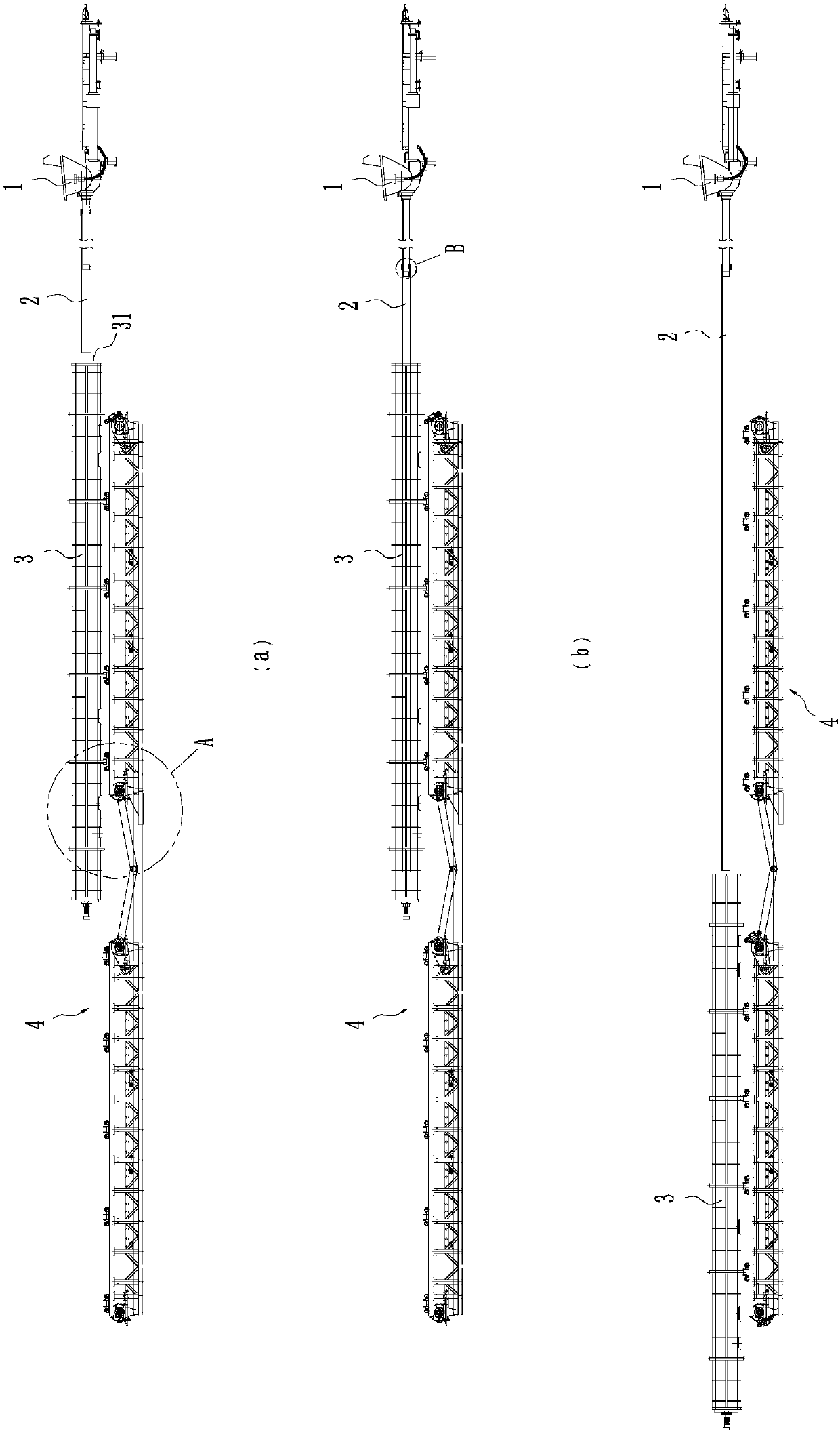
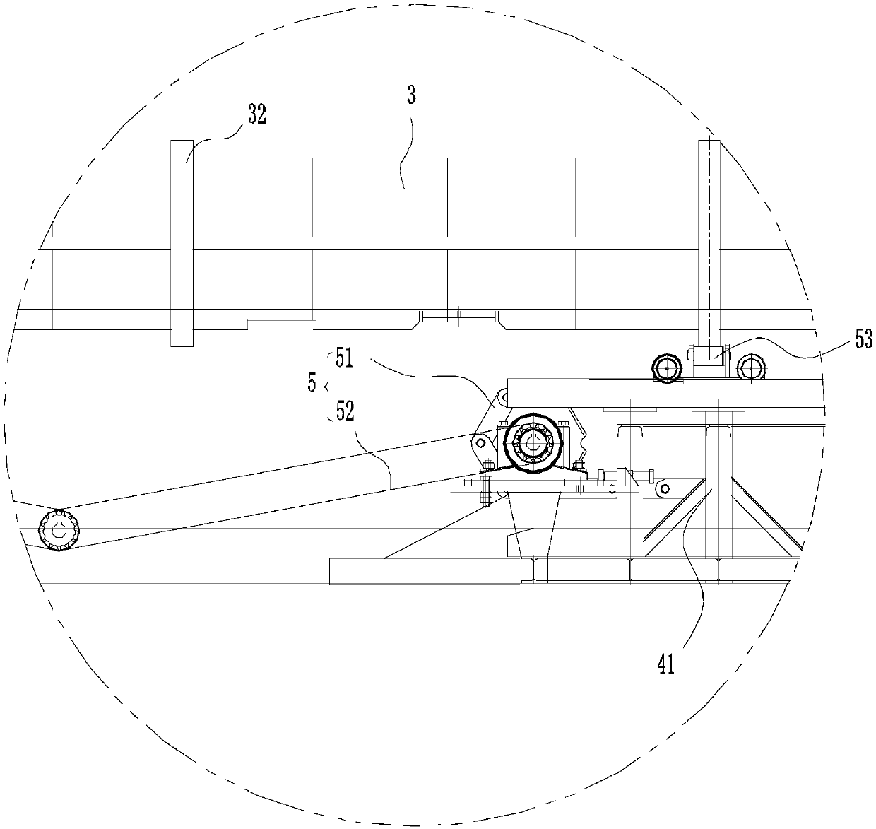
[0045] Such as figure 1 As shown, this embodiment discloses a pumping and distributing equipment for pipe piles. The pumping and distributing equipment for pipe piles includes: a pump 1 , a pumping pipe 2 , a pipe pile mold 3 and a support frame 4 . In order to facilitate the detailed description of the pipe pile pumping and distributing equipment, the direction of the pumping pipe 2 towards the pipe pile form 3 is firstly defined as the front direction. In this embodiment, the rear end of the pumping pipe 2 is connected to the pump 1 and the front end extends to the feed port 31 of the pipe pile form 3 .

[0046] Specifically, the pump machine 1 is equipped with a weighing scale and a control system not shown in the figure, wherein the control system is electrically connected to the weighing scale, and the control system is electrically connected to the power device of the pump machine 1. In this embodiment, it is called The weight scale is used to measure the weight of the ...

Embodiment 2

[0068] In this embodiment, the parts that are the same as in the first embodiment are given the same reference numerals, and the same text descriptions are omitted.

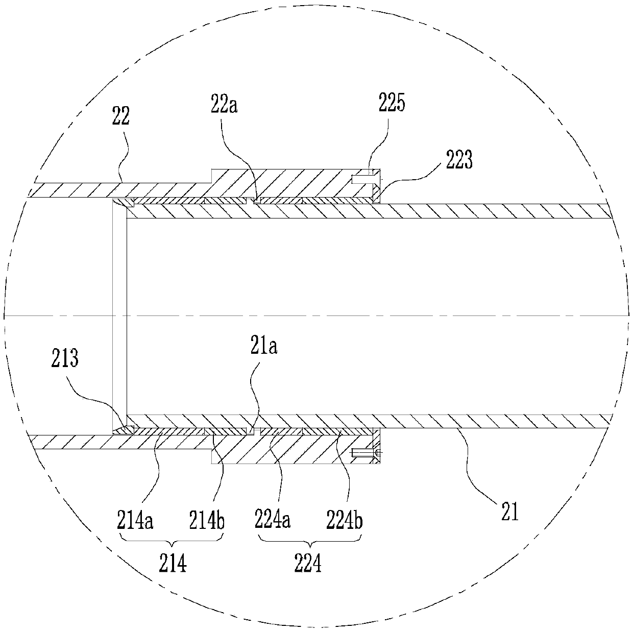
[0069] Compared with Embodiment 1, the telescopic pumping tube 2 provided in this embodiment also has such a structure: Figure 9 and 10 As shown, the first rigid pipe 21 includes a circular first pipe body 211 (ie, the inner pipe body) and a front sealing joint 212 in the shape of a rotary body, the rear end of the front sealing joint 212 and the first pipe body 211 (ie, the inner pipe body). The front end of the pipe body) is screwed or welded and fixed; in this embodiment, the outer annular stopper 21a is located on the front sealing joint 212, and the front sealing assembly 214 is axially sleeved on the front sealing joint 212; the front gland 213 and the first The front end of a pipe body 211 is welded and fixed, of course, for the convenience of maintenance, the front gland 213 and the front end of the fir...

Embodiment 3

[0073] In this embodiment, the parts that are the same as in the second embodiment are given the same reference numerals, and the same text descriptions are omitted.

[0074] Compared with Embodiment 2, the telescopic pumping tube 2 provided in this embodiment also has the following structure:

[0075] Such as Figure 13 As shown, in this embodiment, the pumping pipe 2 also includes a third rigid pipe 23, specifically, the diameter of the third rigid pipe 23 is larger than the diameter of the second rigid pipe 22 so that the third rigid pipe 23 is axially sleeved On the second rigid tube 22 , and the third rigid tube 23 can freely slide in the axial direction relative to the second rigid tube 22 to be fitted, so as to realize further expansion and contraction of the overall length of the pumping tube 2 .

[0076] In this embodiment, the first rigid tube 21 is the innermost rigid tube, the second rigid tube 22 is the outer rigid tube relative to the first rigid tube 21 ; the s...


PUM


Abstract

The invention discloses a telescopic pumping pipe. The telescopic pumping pipe comprises at least two rigid pipes of different pipe diameters, and the rigid pipes are axially installed in a sleeved mode in sequence in the order of small to large pipe diameters, wherein the outer rigid pipes can axially and freely slide relative to the sleeved inner rigid pipes, and anti-off sealing structures aredisposed between the inner rigid pipes and the sleeving outer rigid pipes. When pumping starts, the outer rigid pipes can be extended forward into a pipe pile mold, that is, the overhanging telescopicpumping pipe is supported by the pipe pile mold; and when pumping is completed, the pipe pile mold is separated from the telescopic pumping pipe, and the outer rigid pipes can be retracted toward a pump machine to reduce the overall overhanging length, so that the deflection distortion of the pumping pipe is reduced. Therefore, the overall cost of pipe pile material pumping and distribution equipment is reduced by eliminating existing pumping pipe support structures by the telescopic pumping pipe.

Description

technical field [0001] The invention relates to the field of pipe pile production equipment, in particular to a telescopic pumping pipe. Background technique [0002] The production of concrete pipe piles usually adopts the mold-closing pre-distributing process. The pipe pile formwork is made into a whole, and the concrete is directly transported into the pipe pile form through the pipe pile pumping and distributing equipment. During the distributing process, the concrete delivery pipe and The mold trolleys move relative to each other, and uniform cloth distribution can be achieved by controlling their relative speed. [0003] Such as Chinese utility model patent (CN 204800827 U) discloses a kind of concrete automatic distributing system, and it comprises a base platform, and a guide rail is arranged on this base platform, and one end of guide rail is provided with a concrete pump, and the other end is provided with a distributing vehicle, and the distributing vehicle A met...

Claims


Application Information

Patent Timeline
IPC IPC(8): E04G21/04B28B13/02
CPCB28B13/02E04G21/0418E04G21/0472
Inventor 周兆弟
Owner 周兆弟
Why Eureka
Try Eureka