Yarn drying equipment for textile

A technology for drying equipment and yarn, applied in drying, dryer, lighting and heating equipment and other directions, can solve the problems of residual moisture in yarn and incomplete drying.

Active Publication Date: 2019-09-13
SUZHOU ZHIRUI PHOTOELECTRIC MATERIAL TECH CO LTD
View PDF6 Cites 4 Cited by
  • Summary
  • Abstract
  • Description
  • Claims
  • Application Information

AI Technical Summary

Problems solved by technology

[0003] In order to overcome the disadvantages that the structure of the currently used drying device is relatively simple, people need to manually wind up the dried yarn, and the drying is not thorough, and there is still moisture on the yarn, the technical problem to be solved: provide a A textile yarn drying equipment that can automatically wind up the dried yarn and completely dry the yarn

Method used


Image

  • Yarn drying equipment for textile
  • Yarn drying equipment for textile
  • Yarn drying equipment for textile

Examples


Embodiment 1

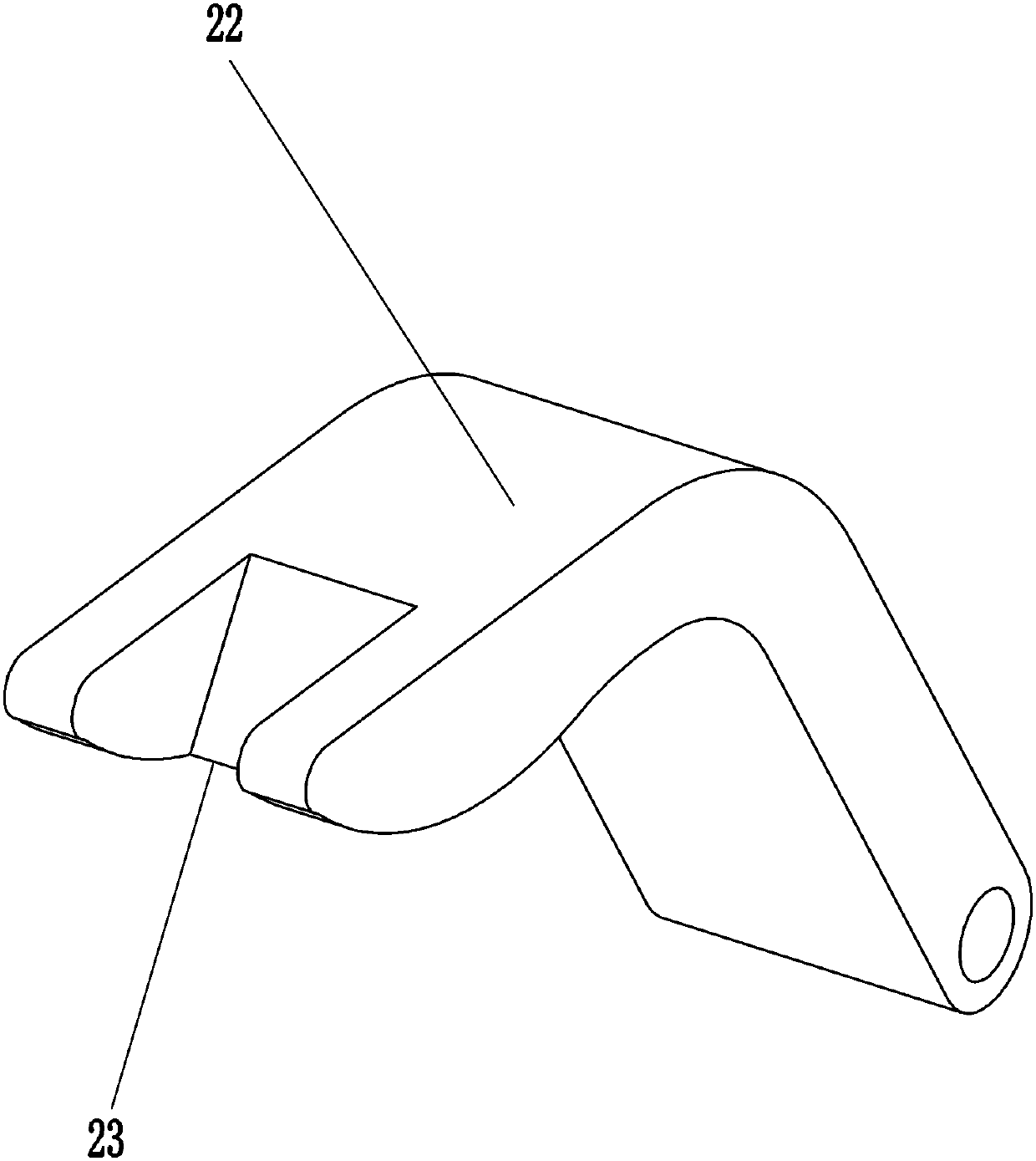
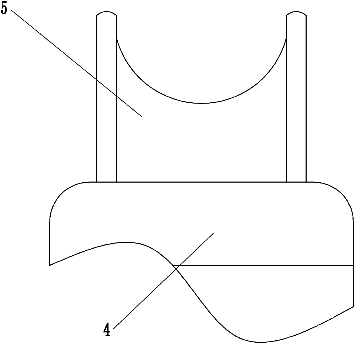
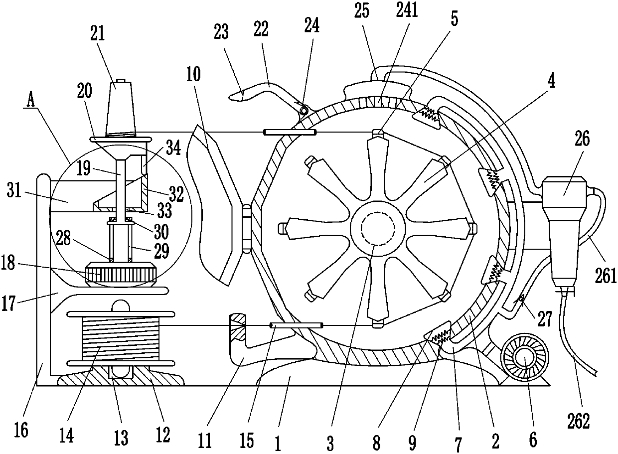
[0016] A kind of textile yarn drying equipment, such as Figure 1-2 As shown, it includes a first base 1, a box body 2, a first motor 3, a polygonal bracket 4, an arc-shaped support block 5, a blower 6, a multi-way pipe 7, a trumpet-shaped air inlet pipe 8, a heating wire 9, and a box door. 10. L-shaped water removal block 11, second base 12, raw material winding wheel 14, hose 15, first pole 16, second pole 17, second motor 18, first shaft 19, turntable 20 and finished product The winding wheel 21, the top of the first base 1 is equipped with a box body 2, the first base 1 is connected to the box body 2 by bolts, the first motor 3 is bolted to the middle of the back side of the box body 2, and the first motor 3 A polygonal bracket 4 is installed on the output shaft of the polygonal bracket 4, and eight arc-shaped support blocks 5 are evenly spaced on the outside of the polygonal bracket 4, and a blower 6 is bolted to the right side of the first base 1, and the blower 6 is con...

Embodiment 2

[0018] A kind of textile yarn drying equipment, such as Figure 1-4 As shown, it includes a first base 1, a box body 2, a first motor 3, a polygonal bracket 4, an arc-shaped support block 5, a blower 6, a multi-way pipe 7, a trumpet-shaped air inlet pipe 8, a heating wire 9, and a box door. 10. L-shaped water removal block 11, second base 12, raw material winding wheel 14, hose 15, first pole 16, second pole 17, second motor 18, first shaft 19, turntable 20 and finished product Winding wheel 21, box body 2 is installed on the top of the first base 1, first motor 3 is bolted to the middle part of the inner rear side of box body 2, polygonal bracket 4 is installed on the output shaft of first motor 3, and the outer side of polygonal bracket 4 is uniform Eight arc-shaped support blocks 5 are fixed at intervals, and a blower 6 is bolted to the right side of the first base 1. The blower 6 is connected with a multi-way pipe 7 for making air flow, and the right side of the box body 2...

Embodiment 3

[0021] A kind of textile yarn drying equipment, such as Figure 1-4As shown, it includes a first base 1, a box body 2, a first motor 3, a polygonal bracket 4, an arc-shaped support block 5, a blower 6, a multi-way pipe 7, a trumpet-shaped air inlet pipe 8, a heating wire 9, and a box door. 10. L-shaped water removal block 11, second base 12, raw material winding wheel 14, hose 15, first pole 16, second pole 17, second motor 18, first shaft 19, turntable 20 and finished product Winding wheel 21, box body 2 is installed on the top of the first base 1, first motor 3 is bolted to the middle part of the inner rear side of box body 2, polygonal bracket 4 is installed on the output shaft of first motor 3, and the outer side of polygonal bracket 4 is uniform Eight arc-shaped support blocks 5 are fixed at intervals, and a blower 6 is bolted to the right side of the first base 1. The blower 6 is connected with a multi-way pipe 7 for making air flow, and the right side of the box body 2 ...


PUM


Abstract

The invention relates to drying equipment, in particular to a yarn drying equipment for textile. The invention aims to provide the yarn drying equipment for the textile which can automatically wind updried yarn and completely dry the yarn. According to the technical scheme, the yarn drying equipment for the textile comprises a first base, a box body, a first motor, a polygonal support, arc-shapedsupporting blocks, an air blower, a multi-way pipe, a trumpet-shaped air inlet pipe, an electric heating wire, a box door and the like; the top of the first base is provided with the box body, the first motor is connected to the middle of the inner rear side of the box body through a bolt, an output shaft of the first motor is provided with the polygonal support, and the eight arc-shaped supporting blocks which are uniformly spaced are fixedly connected to the outer side of the polygonal support. According to the yarn drying equipment for the textile, air can be heated into hot air through the electric heating wire, so that the yarn can be dried; and due to the fact that the yarn is wound around the arc-shaped supporting blocks, the hot air can be uniformly sprayed on the yarn, and then the yarn can be completely dried.

Description

technical field [0001] The invention relates to a drying device, in particular to a drying device for textile yarn. Background technique [0002] In the process of textile processing, the yarn needs to be cleaned. After cleaning, in order not to affect the subsequent processing, the yarn needs to be dried. Now the yarn is generally dried by a drying device, but the drying machine used now The structure of the drying device is relatively simple, and people need to manually wind up the dried yarn, and the drying is not thorough, and there is still moisture on the yarn, so use the drying device to dry the yarn again, which will reduce the work efficiency. Contents of the invention [0003] In order to overcome the disadvantages that the structure of the currently used drying device is relatively simple, people need to manually wind up the dried yarn, and the drying is not thorough, and there is still moisture on the yarn, the technical problem to be solved: provide a The ut...

Claims


Application Information

Patent Timeline
IPC IPC(8): F26B13/10F26B21/00F26B25/00B65H54/44
CPCB65H54/44B65H2701/31F26B13/108F26B21/001F26B21/004F26B25/00
Inventor 不公告发明人
Owner SUZHOU ZHIRUI PHOTOELECTRIC MATERIAL TECH CO LTD
Why Eureka
Try Eureka