Supercharge Your Innovation With Domain-Expert AI Agents!

Convenient-to-use welding spot tensile resistance clamp for measuring welding spot tensile resistance of galvanized welded wire mesh

A tensile and convenient technology, applied in the direction of measuring devices, applying stable tension/pressure to test the strength of materials, instruments, etc., can solve the problems of low test efficiency, inflexibility, and large amount of consumables, etc., to reduce costs, The effect of improving test efficiency and saving test resources

Inactive Publication Date: 2019-09-13
天津津贝尔建筑工程试验检测技术有限公司
View PDF7 Cites 1 Cited by
  • Summary
  • Abstract
  • Description
  • Claims
  • Application Information

AI Technical Summary

Problems solved by technology

In the prior art, in the process of detecting low-carbon steel wire or welded wire mesh with various wire diameter specifications, the jig used to clamp the workpiece of the welded wire mesh is usually a semi-cylindrical structure with a single cross-shaped groove of a fixed size. Fixtures, corresponding to different wire diameters, need to make fixtures of different sizes. The fixtures with this structure have the following defects: 1. Single function, large amount of consumables; 2. Not flexible enough, low test efficiency
[0003] At present, since there is no formed welded spot tensile fixture on the market that can easily adapt to the specification, the engineering and technical personnel of galvanized welded wire mesh production are faced with a research topic that needs to be developed and solved urgently. Spot tension fixture, develop a convenient solder joint tension fixture for measuring the tensile strength of galvanized welded wire mesh solder joints

Method used


Image

  • Convenient-to-use welding spot tensile resistance clamp for measuring welding spot tensile resistance of galvanized welded wire mesh
  • Convenient-to-use welding spot tensile resistance clamp for measuring welding spot tensile resistance of galvanized welded wire mesh

Examples


Embodiment

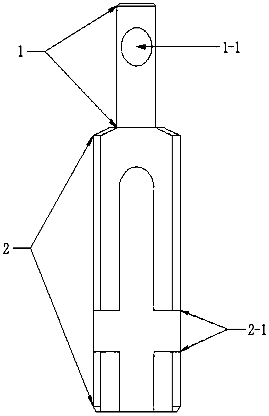
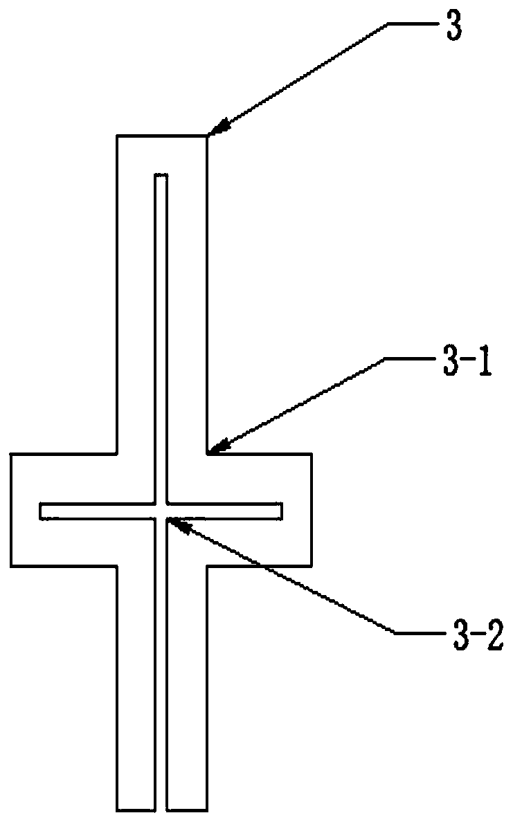
[0025] A convenient solder joint tensile force fixture for measuring the tensile force of solder joints of galvanized welded wire mesh, which is composed of a fixture connector 1, a fixture carrier body 2 and a cross-shaped gasket 3. 1. The structures of the jig carrier body 2 and the cross-shaped gasket 3 are as follows:

[0026] They are as follows:

[0027] Fixture connector 1, such as figure 1 As shown, its external structure is a cylinder, and the cylinder is provided with a hole-shaped bolt connection port 1-1 for connection through a cylindrical bolt, and the bottom of the cylinder is connected with a fixture carrier body 2;

[0028] Fixture carrier 2, such as figure 1 As shown, its shape structure is a half cylinder, the top of the half cylinder is connected to the bottom of the fixture connector 1, and a cross-shaped notch 2-1 is provided at the plane section of the half cylinder;

[0029] Cross spacer 3, such as figure 2 As shown, its external structure is a cro...


PUM

PropertyMeasurementUnit
depthaaaaaaaaaa
diameteraaaaaaaaaa

Abstract

The invention discloses a structure of a convenient-to-use welding spot tensile resistance clamp for measuring welding spot tensile resistance of a galvanized welded wire mesh. The clamp is composed of a clamp connector, a clamp carrier and a cross-shaped gasket, wherein the clamp connector is a cylinder, the diameter and total length of the clamp connector are 18mm and 45mm respectively, and a hole bolt connection opening for connection through a cylindrical bolt is formed in the cylinder; the clamp carrier is a semi-cylinder and is arranged at the bottom of the clamp connector, the diameterand total length of the clamp carrier are 40mm and 105mm respectively, and a cross-shaped slot is formed in a planar section of the clamp carrier; and the appearance structure of the cross-shaped gasket is a cross-shaped body, the center of the cross-shaped body is provided with a cross-shaped core opening with the same thickness as the cross-shaped body, and 16 different dimensions are designed for the specifications of the cross-shaped core opening to correspond to 16 specifications of cross-shaped gaskets. Through the clamp, detection of the welding spot tensile resistance of the welded wire mesh can be performed conveniently and normatively.

Description

technical field [0001] The invention relates to a jig for measuring the tensile strength of solder joints of galvanized welded wire mesh, in particular to a convenient jig for measuring the tensile strength of solder joints of galvanized welded wire mesh, which is used in energy-saving exteriors of civil buildings Testing of external wall insulation systems. Background technique [0002] Galvanized welded wire mesh is made of high-quality low-carbon steel wire, mechanized weaving and welding, and then hot-dip galvanized. It is mainly used for general building exterior walls, pouring concrete, high-rise residential buildings, etc., and plays an important structural role in the insulation system. It has the characteristics of white and bright mesh color, thick zinc layer, uniform mesh, smooth mesh surface, strong tensile strength of solder joints, and high corrosion resistance. In the application process of galvanized welded wire mesh, the tensile strength of solder joints i...

Claims


Application Information

Patent Timeline
Patent Type & Authority Applications(China)
IPC IPC(8): G01N3/08G01N3/04
CPCG01N3/04G01N3/08G01N2203/0282
Inventor 丰江环王欣丽徐杰吴楠郜君董权吴汉森李耀全郭瑶陈红鑫
Owner 天津津贝尔建筑工程试验检测技术有限公司
Features
  • R&D
  • Intellectual Property
  • Life Sciences
  • Materials
  • Tech Scout
  • Unparalleled Data Quality
  • Higher Quality Content
  • 60% Fewer Hallucinations
Learn More