Cleaning heads for floor cleaning machines

A ground cleaning and cleaning head technology, applied in the field of cleaning equipment, can solve problems such as large water output, water leakage, and untidy ground to be cleaned, and achieve the effect of smooth water supply

Active Publication Date: 2021-04-23
SUZHOU EUP ELECTRIC CO LTD
View PDF7 Cites 0 Cited by
  • Summary
  • Abstract
  • Description
  • Claims
  • Application Information

AI Technical Summary

Problems solved by technology

[0004] It can be seen that, in the above structure, since the first water chamber and the second water chamber are both airtight chambers and the first water chamber and the second water chamber communicate with each other, the first regulating port communicates with the outside world and the first water chamber, and the second water chamber communicates with the outside world. The regulating port communicates with the outside world and the second water chamber. When the first regulating port is selectively closed and the second regulating port is opened, the air enters the second water chamber in the form of bubbles under the action of atmospheric pressure. The water level is low, and the pressure of the air bubbles overcoming the fluid is small. Therefore, the air bubbles enter the second water chamber more easily and the water output is larger; when the first regulating port is closed and the second regulating port is closed, the air is in the Under the action of atmospheric pressure, it enters the first water chamber in the form of air bubbles. Since the water level in the first water chamber is higher than that in the second water chamber, the pressure of the air bubbles to overcome the fluid is relatively large. Less water enters the first water cavity, and the water output is small. However, in the above structure, since the two adjustment ports are all set at the bottom of the water tank, it is inevitable that the water in the water tank will leak from the opened adjustment port. conditions that make the floor to be cleaned untidy
If the second regulating port is set on the top wall of the second water chamber, and the first regulating port is opened on the top wall of the first water chamber, then when the first regulating port is closed and the second regulating port is opened, due to the two The water chambers are interconnected and the water level in the first water chamber is higher than the water level in the second water chamber, then the water in the second water chamber will emerge from the second adjustment port, wet the outside of the box, and even enter the interior of the sweeping robot , causing damage to the motor; in addition, if there is a ventilation hole on the water tank, and the ventilation hole is in an open state, the outside air will only enter the water tank from the ventilation hole, and the opened adjustment port and the liquid outlet will In the case of water outflow, the above-mentioned water in the water tank will still leak from the opened adjustment port

Method used


Image

  • Cleaning heads for floor cleaning machines
  • Cleaning heads for floor cleaning machines
  • Cleaning heads for floor cleaning machines

Examples


Embodiment Construction

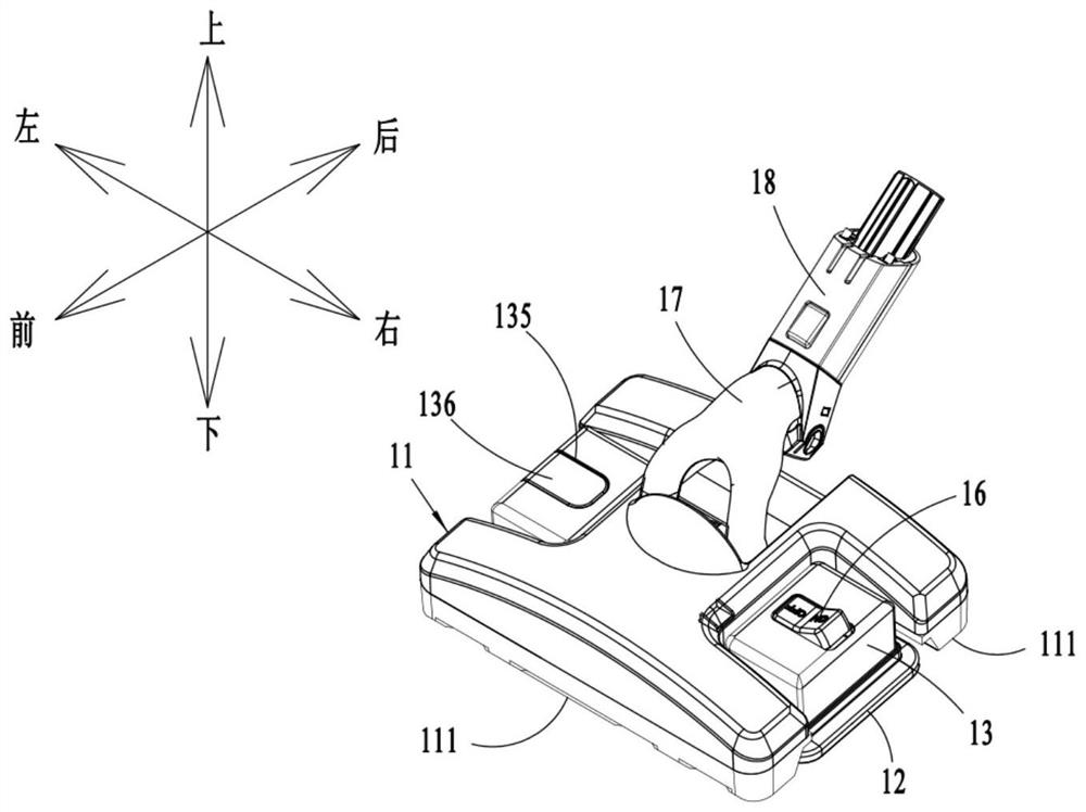
[0044] In order to describe the technical content, structural features, achieved goals and effects of the invention in detail, the following will be described in detail in conjunction with the embodiments and accompanying drawings. Wherein, the upper, lower, left, right, front and rear positional relationships described in this embodiment are related to figure 1The respective positional relationships shown in correspond to each other.

[0045] The cleaning head of the present invention is mainly used on floor cleaning machines, which are equipment for vacuuming and / or cleaning the ground to be cleaned, for example, it can be a wet and dry vacuum cleaner, or a floor washing machine .

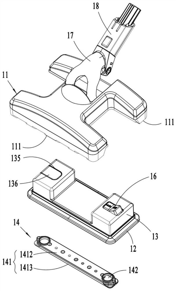
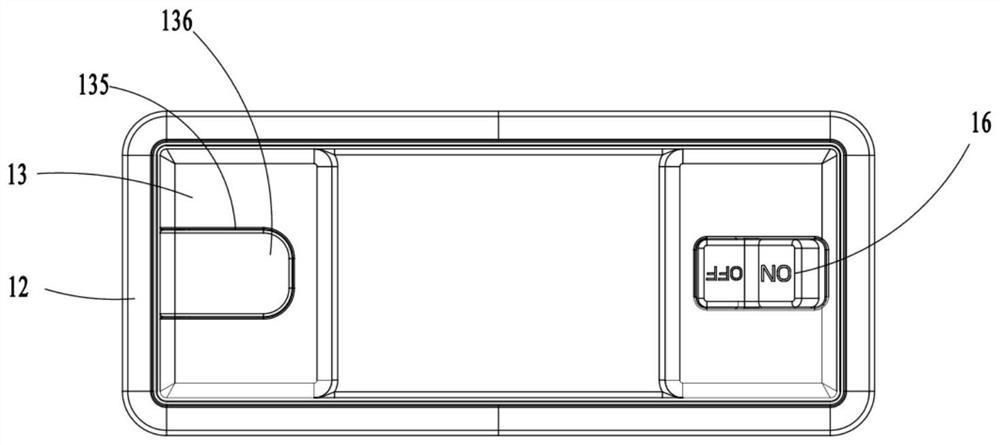
[0046] Such as Figure 1-Figure 2 As shown, the cleaning head includes a cleaning head body 11 , a bottom plate 12 , a water supply tank 13 , a water distributor 14 , a rotary joint 17 and a suction channel 18 .

[0047] Wherein, the rotating connection head 17 is connected to the cleaning hea...


PUM


Abstract

The invention discloses a cleaning head for a floor cleaning machine, which comprises a cleaning head body, a base plate, a water supply tank and a water distributor. At least one suction port is arranged at the bottom of the cleaning head body, and the water supply tank is installed on the cleaning head body and located above the base plate. The inside of the water supply tank has an airtight first chamber, and the lower part is provided with a water outlet. The water distributor is installed on the bottom plate. The water distributor includes a shell, a water inlet opened on the top of the shell, and a second chamber formed inside the shell. , at least one water outlet hole set on the lower bottom of the housing and a vent hole arranged on the upper part of the housing and communicated with the outside world, the volume of the second chamber is smaller than the volume of the first chamber, the first chamber, the water outlet, the inlet The water outlet, the second chamber, and the water outlet hole are connected in sequence. The lower part of the water supply tank is provided with a sealing water port connected to the second chamber. The sealing water port is located at the lower part of the water outlet and extends into the second chamber, making the mop water supply smoother. , and can prevent the water in the water tank from overflowing from the vent hole.

Description

technical field [0001] The invention belongs to the technical field of cleaning equipment, in particular to a cleaning head for a floor cleaning machine. Background technique [0002] In daily life, vacuum cleaners are usually used to absorb dust and other particles on the ground to be cleaned, especially for cleaning rough ground, such as cleaning indoor carpets, wooden floors, etc., and for cleaning smooth ground, such as floor tiles, ceramic tiles, etc., In general, a clean mop is used to scrub the smooth ground with a wet mop to remove stains on its surface. However, such a cleaning method inevitably requires the user to replace the cleaning tool many times to realize the cleaning operation of the surface to be cleaned, which is relatively cumbersome to operate. [0003] The Chinese invention patent application with the publication number CN108852185A discloses a "water tank and automatic cleaning device". The gear adjustment key selectively seals the first adjustment ...

Claims


Application Information

Patent Timeline
Patent Type & Authority Patents(China)
IPC IPC(8): A47L11/28A47L11/40
CPCA47L11/28A47L11/4036A47L11/4083A47L11/4088
Inventor 卞庄
Owner SUZHOU EUP ELECTRIC CO LTD
Why Eureka
Try Eureka