High-speed indexing separator

A divider, high-speed technology, applied in the direction of belt/chain/gear, mechanical equipment, transmission device, etc., can solve the problems of limiting the rotation speed of the divider, high heat of the divider, affecting the service life and safety of the divider, etc. The effect of sliding friction, reducing damage and prolonging service life

Pending Publication Date: 2019-09-17
宁波天相机械制造有限公司
View PDF0 Cites 0 Cited by
  • Summary
  • Abstract
  • Description
  • Claims
  • Application Information

AI Technical Summary

Problems solved by technology

[0003] In the existing intermittent divider, the supporting rib on the input cam includes alternate and continuous stop sections and dividing sections. The two ends of the supporting rib are generally arranged as dividing sections, and the circumference between the supporting rib and the roller on the output turret is linear. Contact, through the alternate contact between the support ribs on both sides of a single roller and the rollers, the cycle of division, stop and division is completed, so as to achieve the purpose of intermittent rotation of the output turret; in actual operation, when performing division, the traditional support ribs and The mating surfaces of the rollers alternate, causing the rollers to switch between forward rotation and reverse rotation. At this time, sliding friction will occur between the rollers and the supporting ribs; since the speed of the traditional splitter can generally reach 500~700r / min, in each The sliding friction that occurs in each division will cause the divider to generate high heat, which will not only seriously affect the service life and safety of the divider, but also greatly limit the rotation speed of the divider

Method used


Image

  • High-speed indexing separator
  • High-speed indexing separator
  • High-speed indexing separator

Examples


Embodiment 1

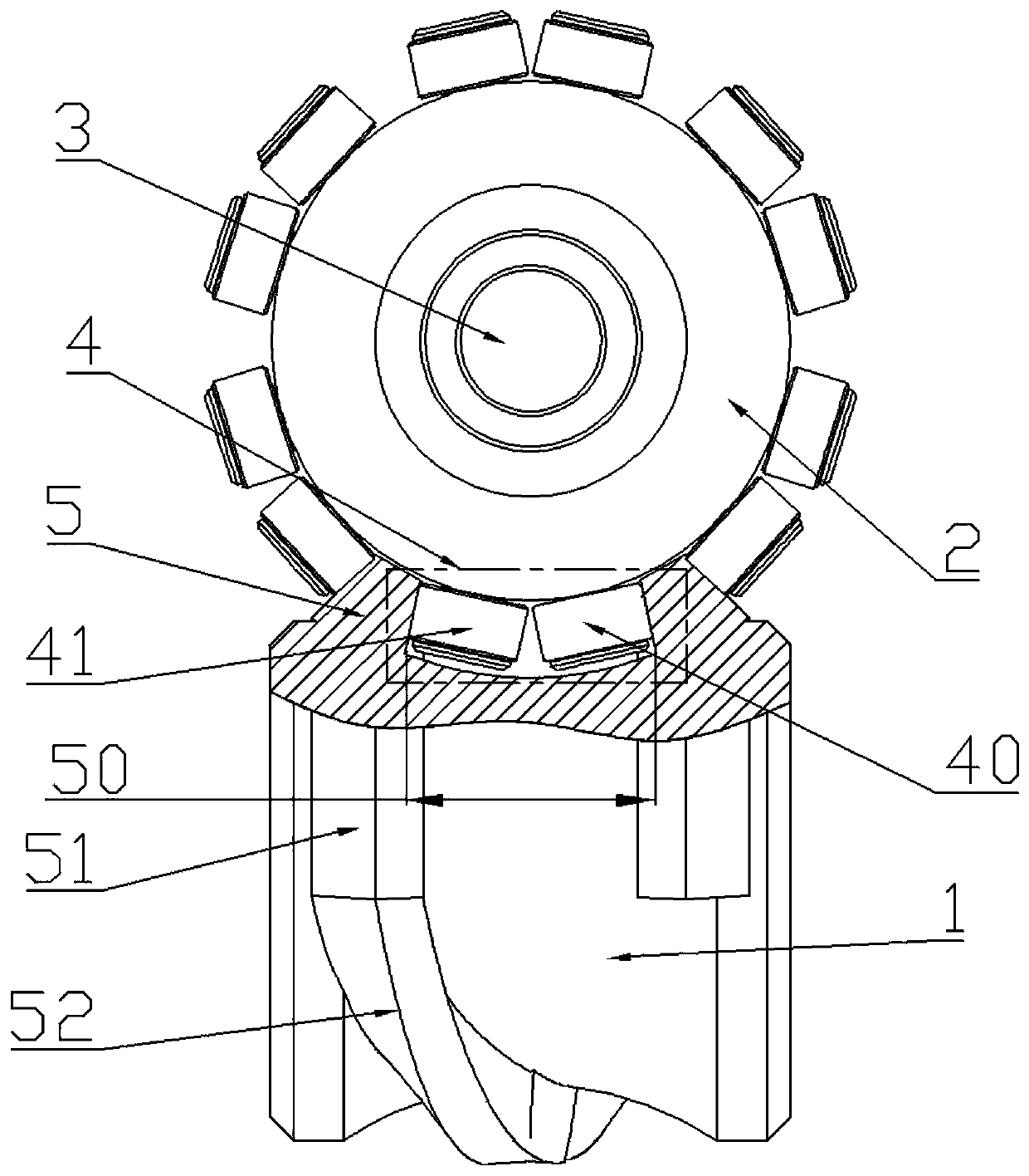
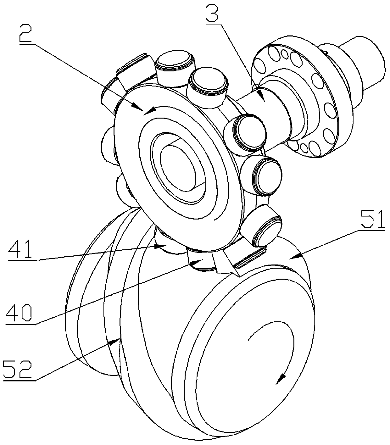
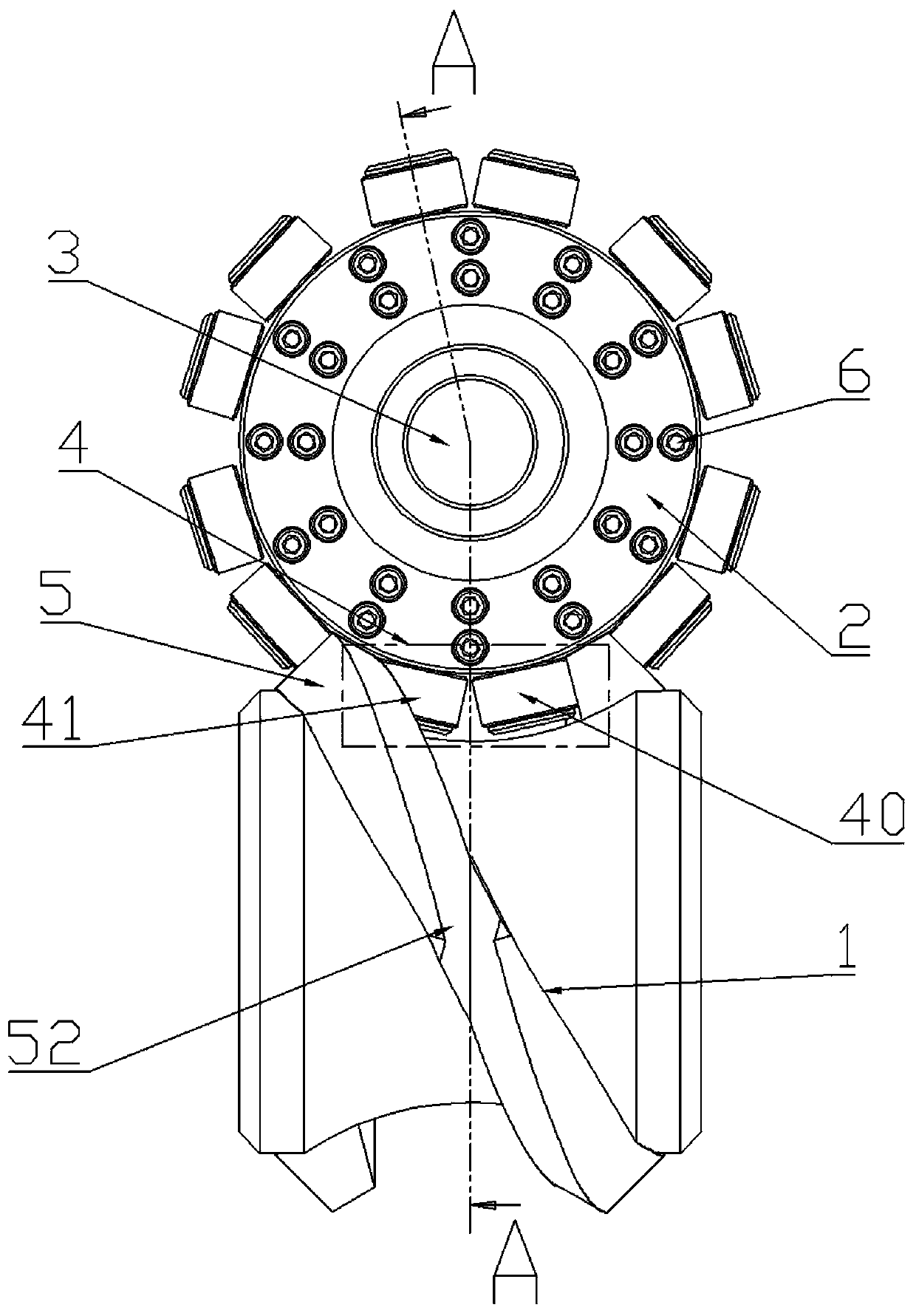
[0018] The high-speed intermittent divider described in this embodiment, such as figure 1 As shown, it includes an input cam 1, an output turret 2 and an output shaft 3, the input cam 1 is in transmission connection with the output turret 2, and the output turret 2 is in transmission connection with the output shaft 3; the output turret 2 A plurality of roller pairs 4 are distributed radially around, and the roller pairs 4 include positive rotation rollers 40 and reverse rotation rollers 41 with the same structure, and the input cam 1 is provided with a supporting rib with a driving curve profile 5. When the input cam 1 and the output turret 2 cooperate with each other, the roller pair 4 is located in the gap 50 formed by the surrounding distribution of the support rib 5, and the forward rotation roller 40 and the reverse rotation roller 41 of the same roller pair 4 are respectively The faces of the support ribs 5 on both sides of the gap 50 are in contact with each other, and...

Embodiment 2

[0023] The high-speed intermittent divider described in this embodiment, such as image 3 , Figure 5 As shown, in addition to the features described in Embodiment 1, in order to facilitate installation and processing, the output turret includes a rotary roller seat 20 and an end cover 21, and the rotary roller seat 20 is connected to the output shaft through transmission. The center of the roller seat 20 is provided with a boss 200, and the center of the end cover 21 is provided with a positioning hole 210. The positioning hole 210 is matched with the boss 200 for positioning, and the end cover 21 is fixedly connected with the rotary roller seat 20. Radial grooves 201 are distributed around the platform 200, and one side of the end cover 21 is provided with auxiliary grooves 211 corresponding to the radial grooves 201, such as Figure 4 , Figure 5 As shown, the radial groove 201 and the auxiliary groove 211 form a plurality of mounting holes 23, and the forward roller 40 a...


PUM


Abstract

The invention discloses a high-speed indexing separator. The high-speed indexing separator comprises a power input cam, a power output rotating tower and a power output shaft, wherein the power input cam is in transmission connection with the power output rotating tower; the power output rotating tower is in transmission connection with the power output shaft; a plurality of roller pairs are distributed around the power output rotating tower in the radial direction, and each roller pair comprises a forward rotating roller and a backward rotating roller which are structured the same; supporting ribs with driving curve outlines are arranged on the power input cam; the roller pairs are positioned in clearances which are formed through the circularly-distributed supporting ribs; the forward rotating rollers and the backward rotating rollers of one roller pair are correspondingly in contact fitting with the surfaces of the supporting ribs at two sides of the clearances; and the forward rotating rollers and the backwards rotating rollers of adjacent roller pairs fit two surfaces of the supporting ribs at the same position. The high-speed indexing separator is long in service life; the rotating speed of the high-speed indexing separator in actual work is doubled that of a traditional separator, so that the efficiency of the separator as well as a production line of the separator can be extremely improved.

Description

technical field [0001] The invention relates to a production equipment, in particular to a high-speed intermittent divider. Background technique [0002] Divider is a mechanism used to realize intermittent motion. It has high indexing accuracy, stable operation, large torque and compact structure. It can perfectly replace traditional cam and ratchet mechanisms and play a huge role in various processing fields. [0003] In the existing intermittent divider, the supporting rib on the input cam includes alternate and continuous stop sections and dividing sections. The two ends of the supporting rib are generally arranged as dividing sections, and the circumference between the supporting rib and the roller on the output turret is linear. Contact, through the alternate contact between the support ribs on both sides of a single roller and the rollers, the cycle of division, stop and division is completed, so as to achieve the purpose of intermittent rotation of the output turret; ...

Claims


Application Information

Patent Timeline
Patent Type & Authority Applications(China)
IPC IPC(8): F16H29/04
CPCF16H29/04
Inventor 朱钧校
Owner 宁波天相机械制造有限公司
Why Eureka
Try Eureka