

Wide beam dielectric resonator antenna
A dielectric resonator and wide-beam technology, which is applied in the direction of antenna, antenna grounding device, antenna grounding switch structure connection, etc., can solve the problems of low radiation efficiency of metal wide-beam antennas and narrow beam width of dielectric resonator antennas, and achieve changes in radiation field, widening the E-plane beamwidth, and widening the effect of the H-plane beamwidth
- Summary
- Abstract
- Description
- Claims
- Application Information
AI Technical Summary
Problems solved by technology
Method used
Image

Examples
Embodiment 1
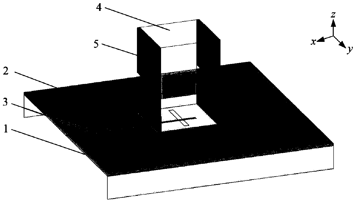
[0031] refer to figure 1 , figure 2 , image 3 and Figure 4
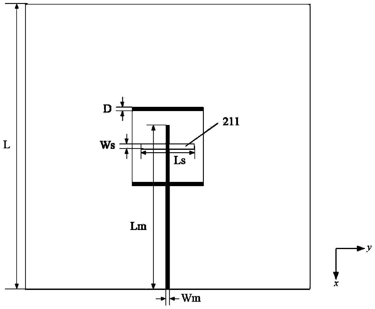
[0032] A wide-beam dielectric resonator antenna, including a dielectric substrate 1, a metal floor 2, a microstrip feeder 3 printed on the lower surface of the dielectric substrate 1, a rectangular dielectric resonator 4 arranged on the upper surface of the metal floor 2, and four rectangular dielectric Sheet 5, the metal floor 2 is composed of a first metal floor 21 and two identical second metal floors 22, the upper surface of the dielectric substrate 1 is printed with the first metal floor 21, and the two sides are respectively provided with Two identical second metal floors 22, the center of the first metal floor 21 is etched with a rectangular slit 211, and the four rectangular dielectric sheets 5 are composed of two first rectangular dielectric sheets 51 of the same structure and two first rectangular dielectric sheets 51 of the same structure The second rectangular dielectric sheet 52 is composed of the...
Embodiment 2
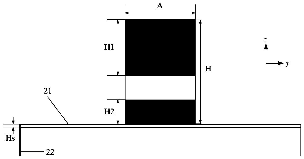
[0043] The four rectangular dielectric sheets 5 adopt a dielectric material with a relative permittivity εr2 of 47, and the thickness is expressed as D, and D is 0.5mm-1.5mm. The length of the cross-sectional rectangle is expressed as A, and A is 20mm-30mm. Wherein, the width of the cross-sectional rectangle of the first rectangular dielectric sheet 51 is denoted as H1, and H1 is 10mm-20mm, and the width of the cross-sectional rectangle of the second rectangular dielectric sheet 52 is denoted as H2, and H2 is 5mm-10mm. In the present invention, D=0.5mm, A=20mm, H1=10mm, H2=5mm.
[0044] The rectangular dielectric resonator 4 adopts a dielectric material with a relative permittivity εr1 of 9.5, its height is expressed as H, and H is 30mm-40mm, and the side length of the cross section is equal to the length A of the cross section of the four rectangular dielectric sheets 5 . In the present invention, H=30mm.
[0045] The rectangular dielectric resonators 4 are located at the ce...
Embodiment 3
[0051] The four rectangular dielectric sheets 5 adopt a dielectric material with a relative permittivity εr2 of 47, and the thickness is expressed as D, and D is 0.5mm-1.5mm. The length of the cross-sectional rectangle is expressed as A, and A is 20mm-30mm. Wherein, the width of the cross-sectional rectangle of the first rectangular dielectric sheet 51 is denoted as H1, and H1 is 10mm-20mm, and the width of the cross-sectional rectangle of the second rectangular dielectric sheet 52 is denoted as H2, and H2 is 5mm-10mm. In the present invention, D=1.5mm, A=30mm, H1=20mm, H2=10mm.
[0052] The rectangular dielectric resonator 4 adopts a dielectric material with a relative permittivity εr1 of 9.5, its height is expressed as H, and H is 30mm-40mm, and the side length of the cross section is equal to the length A of the cross section of the four rectangular dielectric sheets 5 . In the present invention, H=40mm.
[0053] The rectangular dielectric resonators 4 are located at the c...
PUM
| Property | Measurement | Unit |
|---|---|---|
| Thickness | aaaaa | aaaaa |
| Relative permittivity | aaaaa | aaaaa |
Abstract
Description
Claims
Application Information