Electrical connector

A technology of electrical connectors and connectors, which is applied in the direction of connections, circuits, and parts of connection devices, can solve problems such as poor contact, easy crosstalk, and increased production costs, so as to reduce crosstalk, reduce manufacturing processes, cost saving effect

Active Publication Date: 2019-09-17
DEYI PRECISION ELECTRONIC IND CO LTD PANYU
View PDF8 Cites 11 Cited by
  • Summary
  • Abstract
  • Description
  • Claims
  • Application Information

AI Technical Summary

Problems solved by technology

[0005] Since the grounding piece and the grounding terminal are assembled into the tongue plate, there is a gap between the grounding piece and the grounding terminal and the tongue plate, but the grounding piece is separated by elastic The fork is in contact with the grounding terminal. When the electrical connector shakes during use, the fork is likely to have poor contact with the grounding terminal, resulting in failure to achieve normal grounding.
Secondly, since the grounding piece is only located on the lower side of the front end of the first terminal, the grounding piece does not shield the entire contact portion of the differential signal terminal pair, so it does not protect the differential signal terminal pair. The noise signal around the contact part of the signal terminal pair plays a role of shielding, and the differential signal terminal pair emits an electromagnetic field to generate more energy when transmitting signals, which is prone to crosstalk and affects the electrical The signal transmission of the connector, which in turn affects the functional use of the connector
Furthermore, since the electrical connector contacts the grounding terminal through the grounding member to achieve a grounding effect, it is necessary to manufacture two pairs of the differential signal terminals with different shapes during the manufacturing process of the connector. Yes, the three grounding terminals and the grounding piece need to go through multiple manufacturing processes, which increases the production cost

Method used


Image

  • Electrical connector
  • Electrical connector
  • Electrical connector

Examples


Embodiment Construction

[0044] In order to facilitate a better understanding of the purpose, structure, features, and effects of the present invention, the present invention will now be further described in conjunction with the accompanying drawings and specific embodiments.

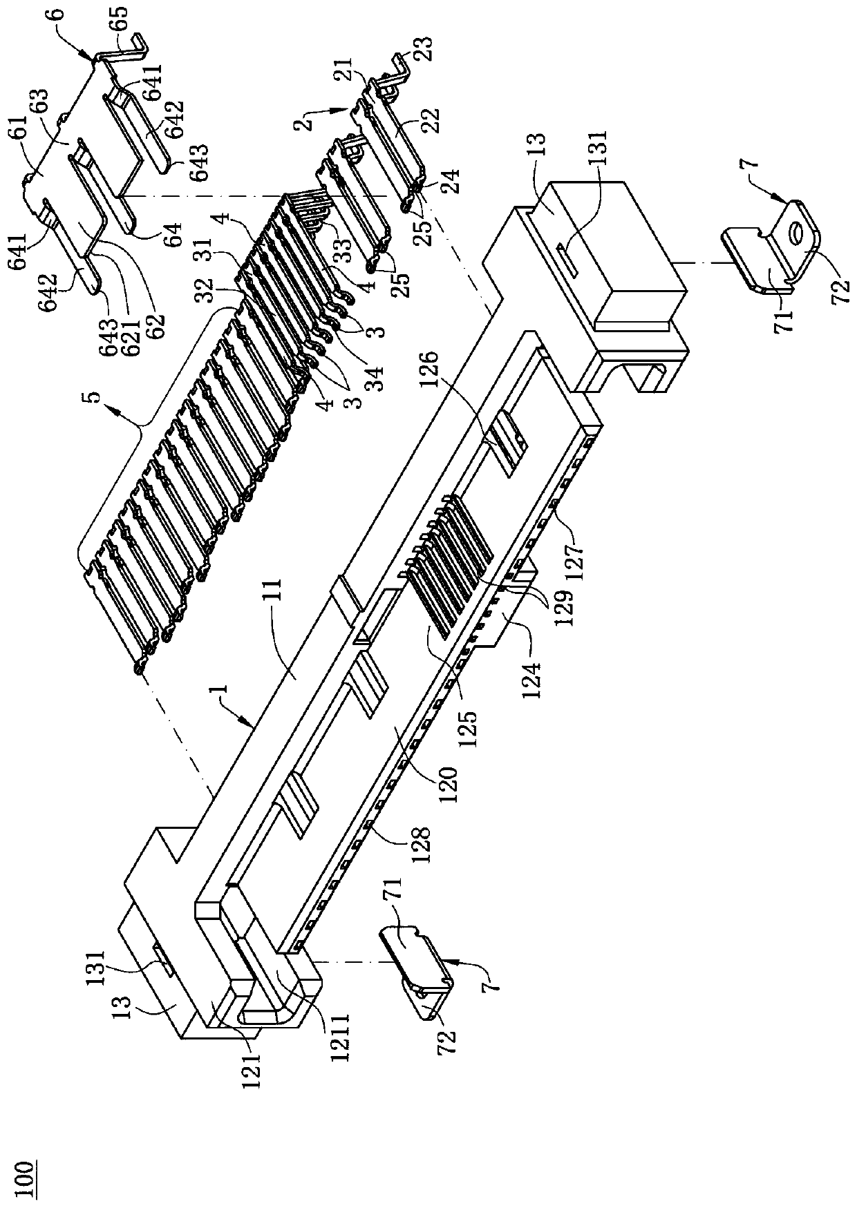
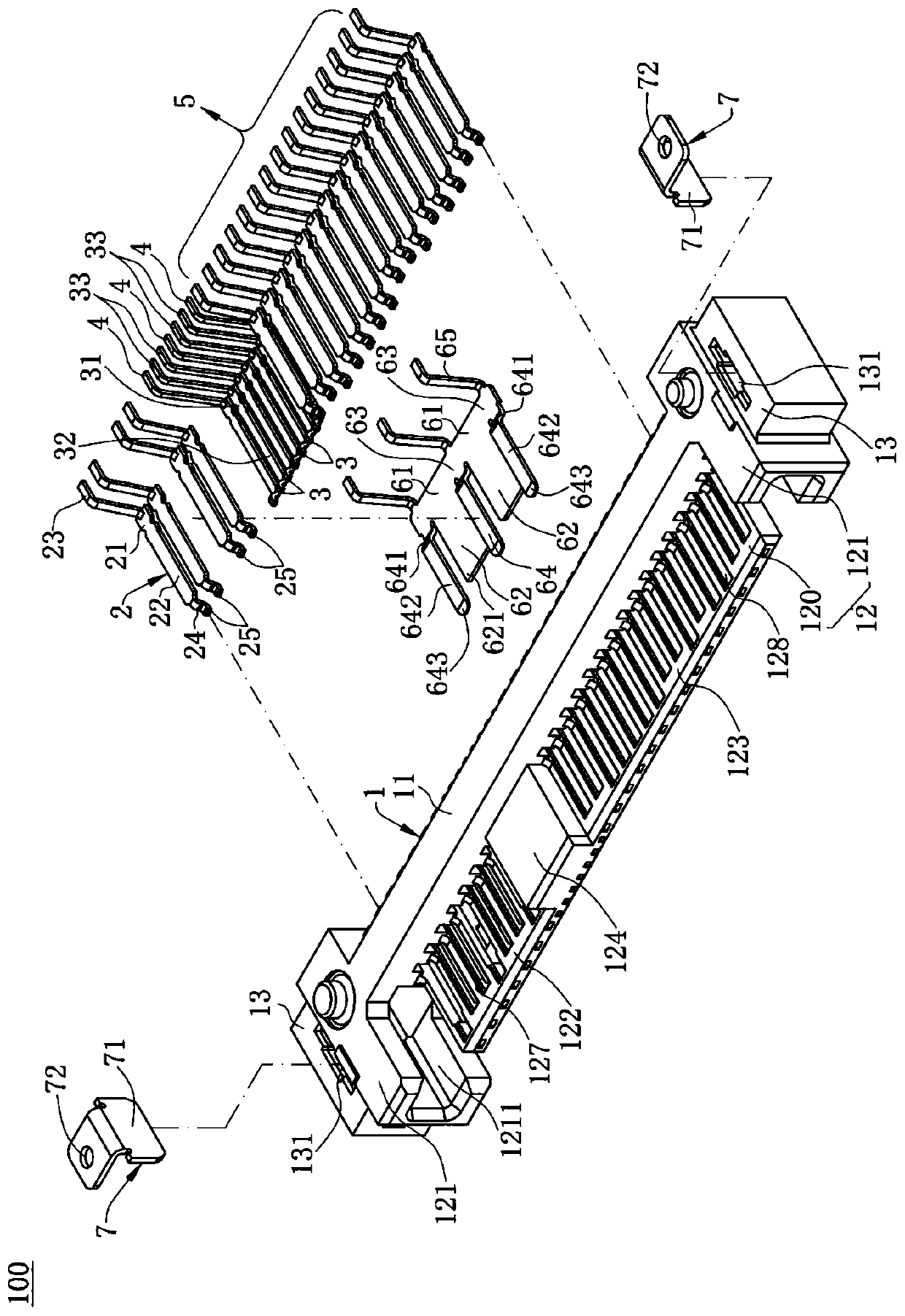
[0045] like figure 1As shown, the electrical connector 100 of the present invention is used for docking with a mating connector (not shown). The electrical connector 100 includes an insulating body 1, a plurality of first signal terminals 2, a plurality of second signal terminals 3, a plurality of grounding terminals 4, a plurality of power terminals 5 and a Shield 6. Two metal parts 7 are inserted on both sides of the insulating body 1, and the metal parts 7 are used to fix the insulating body 1 on a circuit board (not shown).

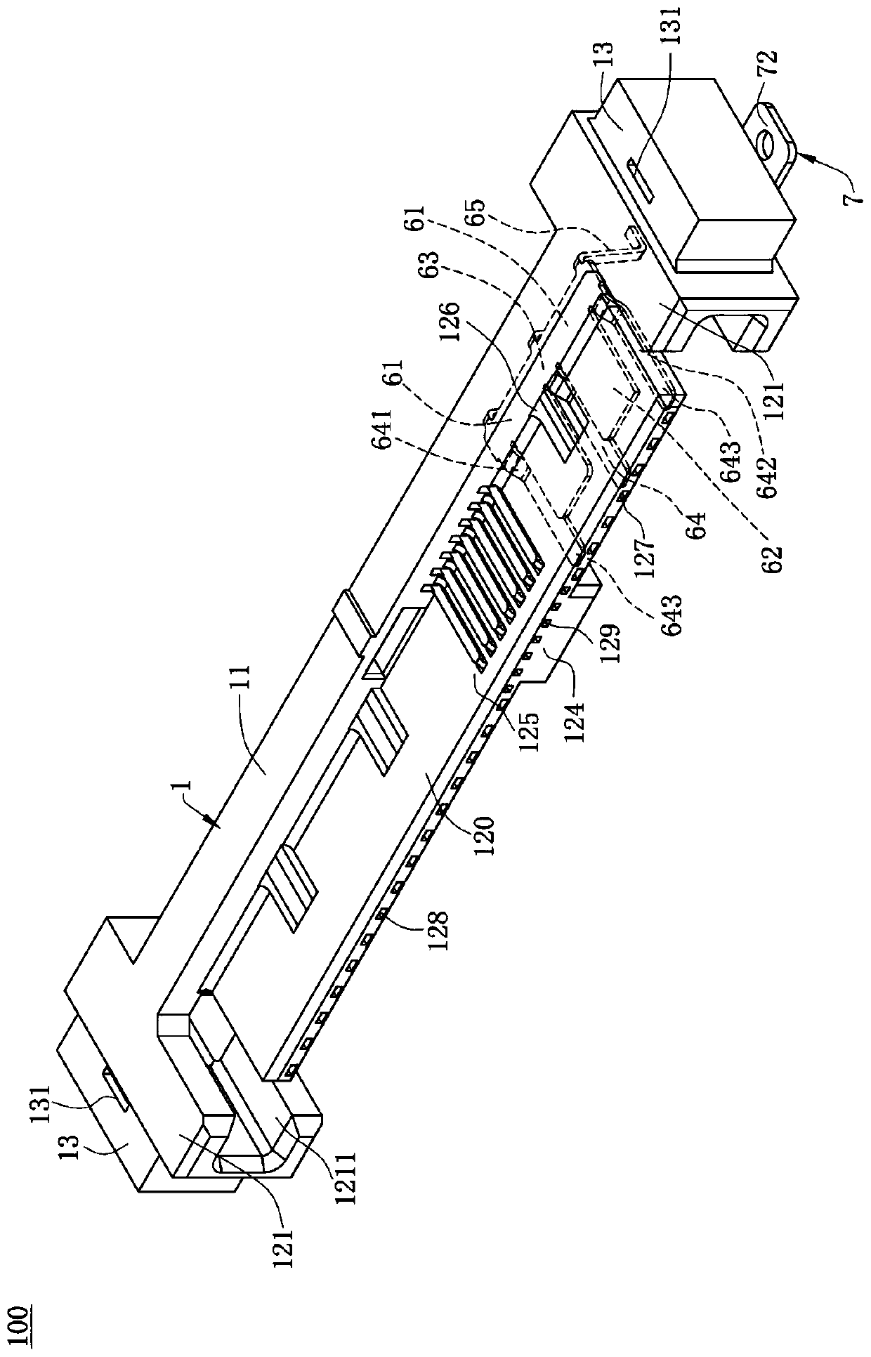
[0046] like Figure 1 to Figure 4 As shown, the insulative body 1 is elongated. The insulative body 1 includes a base 11 and a butt joint 12. The butt joint 12 includes a tongue 120 extending forwar...


PUM


Abstract

The invention discloses an electrical connector for connecting with a mating connector. A plurality of first signal terminals are disposed on an insulating body in a lateral direction, and each of the first signal terminals has a first contact portion exposed out of a tongue plate and a first front end portion which bends and extends from a front end of the first contact portion in a vertical direction. A shielding member is received in the insulating body, the shielding member comprises at least one main body portion, a shielding portion extends forward from the main body portion, the shielding portion is received in the tongue plate, at least one connecting portion transversely extends from the main body portion, a grounding portion extends forward from the connecting portion and is used for connecting the mating connector, the shielding portion shields one side of the first contact portion, the grounding portion and the shielding portion are spaced apart in the lateral direction, and the projection of the shielding portion overlaps with a projection portion of the first front end portion as viewed in a projection direction from the front to the back. The problem of poor contact can be avoided, the shielding effect is good and more stable, the shielding portion shields one side of the first contact portion with a close distance, and the crosstalk can be effectively reduced.

Description

[0001] 【Technical field】 [0002] The invention relates to an electrical connector, in particular to an electrical connector with a shield. [0003] 【Background technique】 [0004] Chinese patent application number CN201120136325.4 discloses an electrical connector. The electrical connector includes an insulating body, a tongue extending forward from the insulating body, seven first terminals, and the seven first terminals include two pairs of differential signal terminals and three grounding terminals arranged alternately. . A ground member, said ground member comprising an elongated base, a plurality of bifurcations disposed perpendicularly to said base. The grounding piece and the first terminal are respectively assembled in the tongue plate, the grounding piece is located on the lower side of the front end of the first terminal, and is connected with the front end of the grounding terminal through the elastic fork. contact to ground. [0005] Since the grounding piece a...

Claims


Application Information

Patent Timeline
Patent Type & Authority Applications(China)
IPC IPC(8): H01R13/6461H01R13/6581H01R13/02H01R13/502H01R12/71
CPCH01R12/716H01R13/02H01R13/502H01R13/6461H01R13/6581
Inventor 冯晓曹永金
Owner DEYI PRECISION ELECTRONIC IND CO LTD PANYU
Why Eureka
Try Eureka