Backlight detecting mold

A backlight detection and mold technology, applied in optics, nonlinear optics, instruments, etc., can solve the problems of inconvenient use, small light-transmitting area, and high cost, saving mold space, avoiding frequent replacement, and effectively covering. Effect

Active Publication Date: 2008-10-01
K TRONICS (SUZHOU) TECH CO LTD +1
View PDF3 Cites 3 Cited by
  • Summary
  • Abstract
  • Description
  • Claims
  • Application Information

AI Technical Summary

Problems solved by technology

In practical applications, after the 17-inch display is tested, a 17-inch backlight detection mold is used to test a 20.1-inch screen. Not only the screen to be tested cannot be placed on the backlight covering mold 6, but also the area ratio of the light-transmitting area of ​​the backlight covering mold 6 is determined by the The screen to be tested is small, and inspectors cannot see the surrounding images of the screen under test, which seriously affects the quality of the screen. Therefore, it is necessary to replace the 20.1inch backlight

Method used


Image

  • Backlight detecting mold
  • Backlight detecting mold
  • Backlight detecting mold

Examples


Embodiment 1

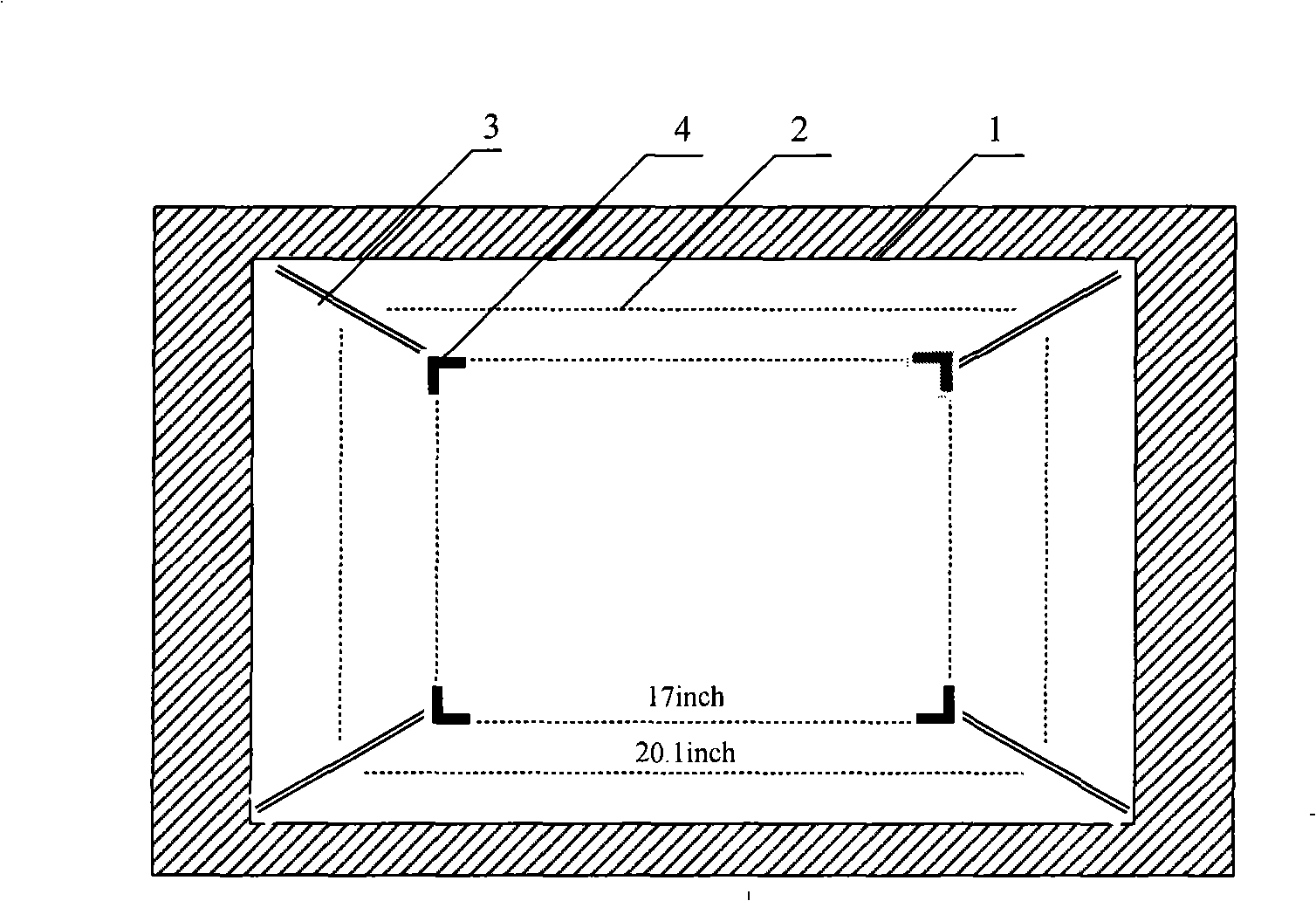
[0020] Such as image 3 , 4 , 5, the backlight detection mold includes a frame 1, a detection base plate 2, a hole 3, a clamp block 4, and a blocking sheet 5. The detection base plate 2 is embedded in the frame 1, and a section of hole 3 is opened on the detection base plate 2 along a diagonal line from four apexes to the center of the detection base plate 2, and a clamping block 4 is slid on the hole 3, and the clamping block 4 is on the hole 3 Slide, and fix on the hole 3 by clamping the upper and lower parts of the clamp block 4; there is also a gasket on the clamp block 4, which is used to resist the screen under test, so that the screen under test is placed on the detection base plate 2 relatively stably superior. The detection bottom plate is made of transparent material acrylic; the detection bottom plate 2 is provided with a size mark showing the measured area.

[0021] When testing, for example, first detect the 17inch TFT-LCD, such as Figure 4 As shown, first sl...

Embodiment 2

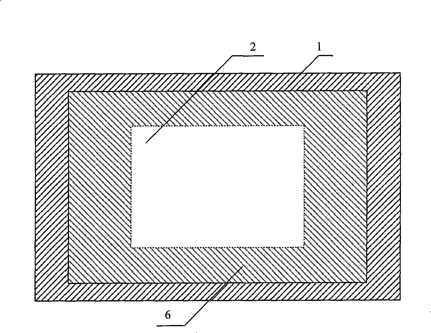
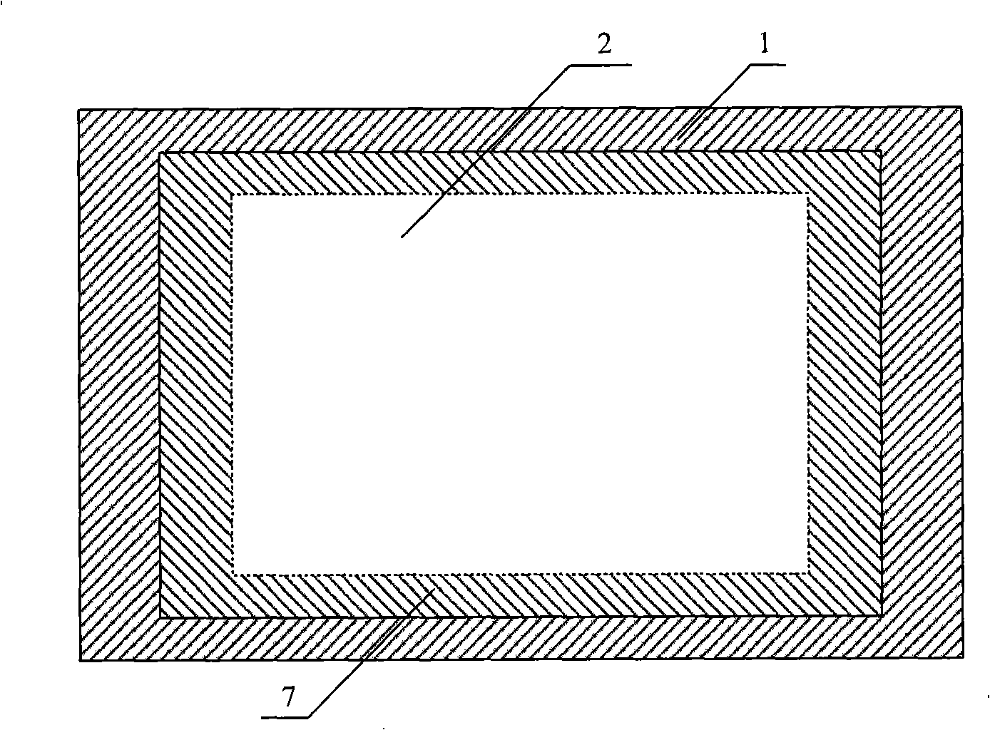
[0023] Based on Embodiment 1, the shielding sheet 5' is rolled into the frame 1, the shielding sheet 5' is connected to the clamping block 4, and can move together with the clamping block 4, and the shielding sheet 5' extends outward when the clamping block 4 moves outward , when the clamp block 4 moves inward, the blocking piece 5' retracts inwardly, covering the part of the detection base plate 2 that is not covered by the screen under test in a manner of advancing and retreating at the same time; logo.

[0024] When testing, for example, first check the 20.1inch TFT-LCD, such as Figure 6 As shown, slide the clamp block 4 on the place marked with a size of 20.1 inches, and place the TFT-LCD under test on the detection base plate 2. At this time, the gasket on the clamp block 4 has been pressed against the TFT-LCD under test, so that Its fixation will not shift left or right or up and down; and because the shielding piece 5' is connected with the clamp block 4, the exposed ...

Embodiment 3

[0026] Based on Embodiment 1 or 2, 2 or more holes can be opened in different positions of the detection base plate as required, and clamp blocks can be slid on the holes to meet the requirements of fixing the screen under test. For example, two holes can be opened on the detection base plate, and clamping blocks can be slid on the holes. If the method of forming a certain angle with the horizontal plane is adopted during the image quality inspection, at least one hole may be provided at the lower edge of the inspection base plate.


PUM


Abstract

The present invention relates to a backlight detecting mold which comprises an antistatic transparent detecting baseboard which is inlaid in a framework. The detecting baseboard is provided with two or more holes from edge to the center. The hole is slidingly provided with a clamp block. The mold is also provided with the opaque antistatic blocking piece which shields the part which is not shielded by the detecting screen. The invention also provides an image quality detecting device which is provided with the backlight detecting mold. The backlight detecting mold according to the invention can realize the fixed putting of the screen when the image quality of the display screen is detected, and effectively shield the light of backlight source.

Description

technical field [0001] The invention relates to a backlight detection mold, in particular to a backlight detection mold with the function of adjusting the area to be tested, which can complete the fixed placement of the screen during the quality detection of the display screen and effectively cover the backlight light. Background technique [0002] With the continuous advancement of audio-visual technology, the display screens of audio-visual products are gradually developing in the direction of high-definition and multiple specifications. Currently, liquid crystal displays (Liquid Crystal Displays; hereinafter referred to as LCDs) are the mainstream of displays on the market. As market competition becomes more and more fierce, both manufacturers and consumers have put forward higher requirements on the quality of monitors, especially in terms of the quality of the display screens of monitors. In order to ensure the quality, the necessary display screen inspection is requir...

Claims


Application Information

Patent Timeline
IPC IPC(8): G02F1/13
Inventor 王洁琼
Owner K TRONICS (SUZHOU) TECH CO LTD
Why Eureka
Try Eureka