Eureka AIR delivers breakthrough ideas for toughest innovation challenges, trusted by R&D personnel around the world.

Screw locking method and screw locking equipment

A technology of screw locking and screwing, which is applied in the direction of metal processing equipment, metal processing, manufacturing tools, etc., can solve problems such as tilt, screw skew, screw offset, etc., to ensure the quality of locking, improve effectiveness, and increase efficiency Effect

Pending Publication Date: 2020-12-11
JIANGSU XINTIMU INTELLIGENT EQUIP CO LTD
View PDF1 Cites 4 Cited by
  • Summary
  • Abstract
  • Description
  • Claims
  • Application Information

AI Technical Summary

Problems solved by technology

[0004] The problem with this structure is that after the adsorption tube absorbs the screw, it cannot ensure that the twist transmission groove on the end surface of the screw is directly opposite to the front end of the bit. For example, the bit is a cross batch or its front end is a tripod; It cannot be ensured that each fork of the cross front end of the bit corresponds to each fork of the torsion transmission groove, so that the front end of the bit cannot be effectively inserted into the torsion transmission groove to realize the torsion transmission connection
At this time, when the screw is moved to the waiting position for locking, since the screw will touch the waiting position first, if the position control accuracy is not high, there is a risk that the screw will be skewed in the hole
At this time, when the bit is started to lock again, the rotational force of the bit can easily cause the screw to shift and tilt. The accumulation of these position deviations will cause the locking quality of the screw to fail to meet the requirements.

Method used

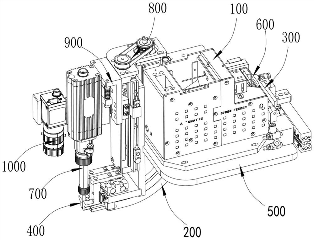
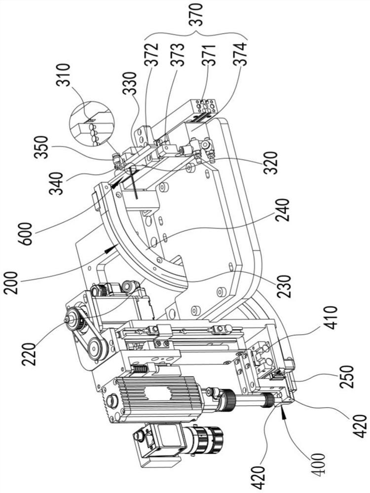
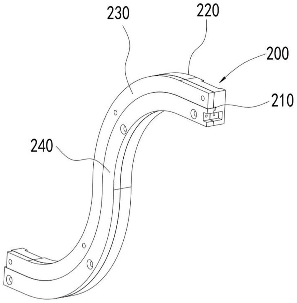

Image

  • Screw locking method and screw locking equipment
  • Screw locking method and screw locking equipment
  • Screw locking method and screw locking equipment

Examples


Embodiment Construction

[0068] Objects, advantages and features of the present invention will be illustrated and explained by the following non-limiting description of preferred embodiments. These embodiments are only typical examples of applying the technical solutions of the present invention, and all technical solutions formed by adopting equivalent replacements or equivalent transformations fall within the protection scope of the present invention.

[0069] In the description of the scheme, it should be noted that the terms "center", "upper", "lower", "left", "right", "front", "rear", "vertical", "horizontal", " The orientation or positional relationship indicated by "inner", "outer", etc. is based on the orientation or positional relationship shown in the drawings, and is only for the convenience of description and simplification of description, rather than indicating or implying that the device or element referred to must have a specific orientation , constructed and operated in a particular or...


PUM


Abstract

The invention discloses a screw locking method and screw locking equipment. The screw locking method comprises the following steps of making a bit of a screwdriver be coaxial with a screw in a loadingposition and making a front end of the bit protrude outside a surface where a front end of an air pipe of the screwdriver and a tail end surface of the screw are attached, wherein a length from the front end of the bit protruding outside a leaning surface is equivalent to a depth of a torque transmission groove in the tail end surface of the screw; forming a negative pressure in a through hole coaxial with the bit at the front end of the air pipe to adsorb the screw; and keeping the negative pressure at the through hole of the air pipe, wherein the bit rotates at a low speed. According to thescheme, before the screw is locked, the bit rotates at the low speed first. In the rotating process of the front end of the bit, the screw can enable the front end of the bit to be inserted into thetorque transmission groove to achieve a torque transmission connection under a suction effect, and the screw can be positioned by the bit when the screw is locked, so that a condition of inclination when the screw is in contact with a to-be-connected hole is avoided. Therefore, the locking quality is guaranteed effectively, the locking effectiveness is improved and the multi-point locking efficiency is improved.

Description

technical field [0001] The invention relates to the field of screw machines, in particular to a screw locking method and screw locking equipment. Background technique [0002] The screw machine is a small machine that automatically locks screws. Its action structure can generally be divided into two parts: the feeding part and the electric batch part. The feeding part is responsible for screening and providing screws, and the electric batch part is responsible for taking screws and locking screws. The generation of the machine not only improves the working efficiency but also reduces the intensity of manual work. [0003] In the suction screw machine, the screw is usually blown into the screw jaw through a hose, and then the screw is adsorbed to the bit by the suction tube on the screwdriver, and then locked. [0004] The problem with this structure is that after the adsorption tube absorbs the screw, it cannot ensure that the twist transmission groove on the end surface of...

Claims


Application Information

Patent Timeline
Patent Type & Authority Applications(China)
IPC IPC(8): B23P19/06B23P19/00
CPCB23P19/001B23P19/06
Inventor 季荣叶际勃刘深龙谭敏章赟孙凯杨志勇范锦宇孙淮扬卢赛赛钱浩东周立静李风武
Owner JIANGSU XINTIMU INTELLIGENT EQUIP CO LTD
Why Eureka
Eureka Blog
Learn More