
Camera Pupil Aberration Correction Method Based on Light Field Coding

A correction method and pupil image technology, which is applied in the field of precision measurement, can solve problems such as the influence of three-dimensional measurement accuracy, pupil aberration, and the inability of the pinhole model to perfectly express the relationship between the camera and the object image, so as to eliminate pupil aberration, The effect of overcoming direction ambiguity and improving measurement accuracy

Active Publication Date: 2020-05-26
FUDAN UNIV
View PDF5 Cites 0 Cited by
  • Summary
  • Abstract
  • Description
  • Claims
  • Application Information

AI Technical Summary

Problems solved by technology

However, since the pupil of the camera lens has a certain size, this assumption will produce pupil aberration, and the calculated light position and direction will contain obvious deviations, so the pinhole model cannot perfectly express the object-image relationship of the camera. The measurement accuracy is seriously affected

Method used


Image

  • Camera Pupil Aberration Correction Method Based on Light Field Coding
  • Camera Pupil Aberration Correction Method Based on Light Field Coding
  • Camera Pupil Aberration Correction Method Based on Light Field Coding

Examples


Embodiment

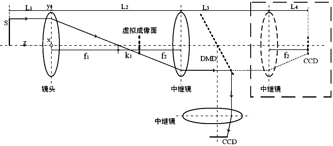
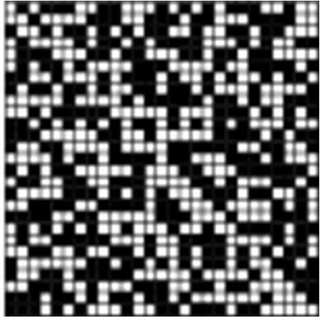
[0024] Embodiment 1: In the measurement process, build a suitable imaging optical path, such as figure 1 shown. In the optical path, the light from the object side is focused on the virtual imaging surface by the primary mirror, and then the converged light is converted into parallel light by the first relay mirror and projected on the DMD. The DMD turns the light path and converges it on the CCD for imaging , the mirror image of the second relay mirror and CCD is inside the dotted frame. L1 is the object distance, L2=f1+k1+f2, where f1 is the focal length of the main mirror, f2 is the focal length of the relay mirror, k1 is the diffraction distance, L3 is the distance between the relay mirrors, and L4 is the focal length of the relay mirror. The specific optical path parameters are shown in Table 1. Use DMD to perform 27×27 Hadamard encoding (namely the observation matrix Φ), and collect the encoded image. The encoding pattern is as follows figure 2 shown. The CCD pixel ...


PUM


Abstract

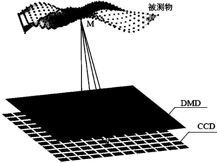
The invention belongs to the technical field of precision measurement, and particularly relates to a camera pupil aberration correction method based on light field coding. The camera pupil aberration correction method comprises the steps: in order to overcome pupil aberration of a pinhole camera, determining each imaging light ray, and using a four-dimensional function (x, y, u and v) to describe an imaging light field, (x and y) represents image point coordinates, and (u and v) represents coordinates of the light rays on a pupil, namely the direction of the light rays; carrying out binarization pupil coding by adopting a digital micromirror array; based on the compressed sensing idea, solving a light field matrix through total variation optimization; and calculating the pupil coordinates (u, v) corresponding to each image point (x, y), and effectively correcting the pupil aberration of the camera in combination with a camera calibration result, so that a camera model conforming to the actual imaging process is constructed. According to the camera pupil aberration correction method, pupil aberration caused by pinhole imaging assumption can be effectively eliminated, and direction ambiguity of monocular vision is overcome, and the direction of imaging light is accurately calculated; and the camera pupil aberration correction method is of great significance for improving the measurement precision of the photogrammetry technology.

Description

technical field [0001] The invention belongs to the technical field of precision measurement, in particular to a camera pupil aberration correction method based on light field coding. Background technique [0002] In modern precision measurement, photogrammetry is a commonly used 3D shape measurement technique. Photogrammetry is mainly divided into two categories: surface 3D measurement techniques for diffuse reflection and surface 3D measurement techniques for specular reflection. The former is typically represented by triangulation, especially fringe projection technology is widely used in industrial precision inspection. Its 3D reconstruction methods mainly include stereo vision and phase-height mapping. For specularly reflective surfaces, phase measurement deflection is commonly used. Because of its simple measurement system, large dynamic range, and strong anti-interference ability, it can be used for the measurement of complex surfaces, and has attracted extensive a...

Claims


Application Information

Patent Timeline
Patent Type & Authority Patents(China)
IPC IPC(8): H04N17/00G06T7/80
CPCG06T7/80H04N17/002
Inventor 张祥朝牛振岐徐敏
Owner FUDAN UNIV
Learn More