Sorting screen surface material status monitoring system and control method thereof and combine harvester

A condition monitoring system, a technology of cleaning and screening, applied in the direction of harvesters, cutters, agricultural machinery and implements, etc., can solve problems such as difficulties and the accumulation of grain exudates

Active Publication Date: 2019-09-20
JIANGSU UNIV
View PDF14 Cites 10 Cited by
  • Summary
  • Abstract
  • Description
  • Claims
  • Application Information

AI Technical Summary

Problems solved by technology

[0006] Aiming at the deficiencies in the prior art, in order to solve the problem that the grain exudates accumulate on the sieve surface due to factors such as a sudden increase in feeding amount during the operation of the combine harvester, the present invention provides a cleaning sieve surface The material state monitoring system and control method and the combine harvester judge whether there is difficulty in grain sieving by monitoring the change of the airflow through the sieve in the space above the cleaning sieve and the change of the torque of the grain auger

Method used


Image

  • Sorting screen surface material status monitoring system and control method thereof and combine harvester
  • Sorting screen surface material status monitoring system and control method thereof and combine harvester
  • Sorting screen surface material status monitoring system and control method thereof and combine harvester

Examples


Embodiment 1

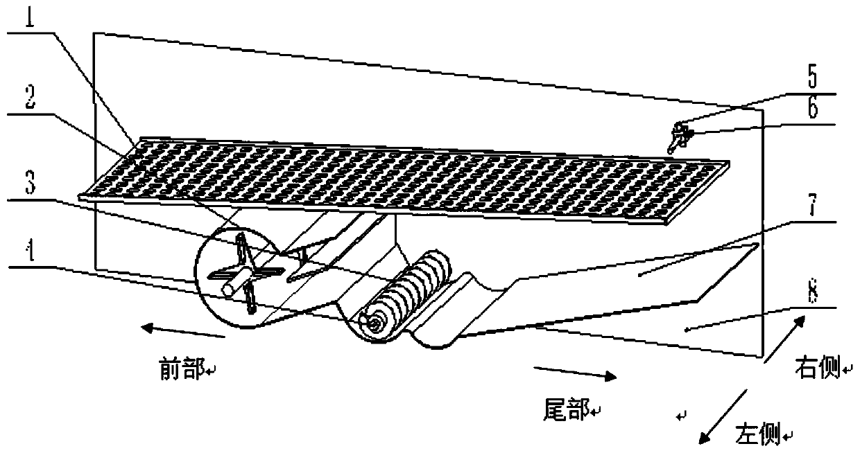
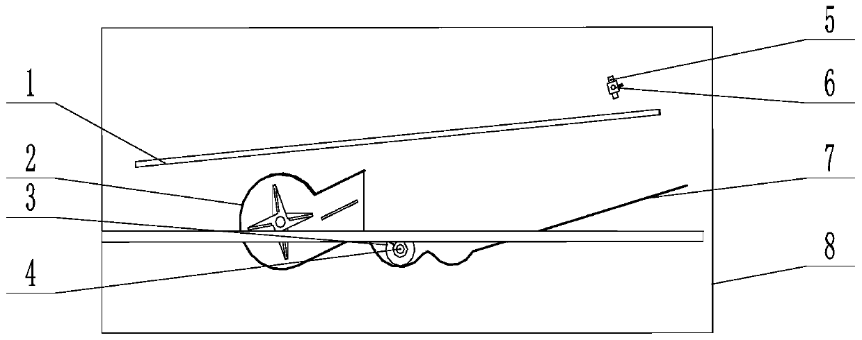
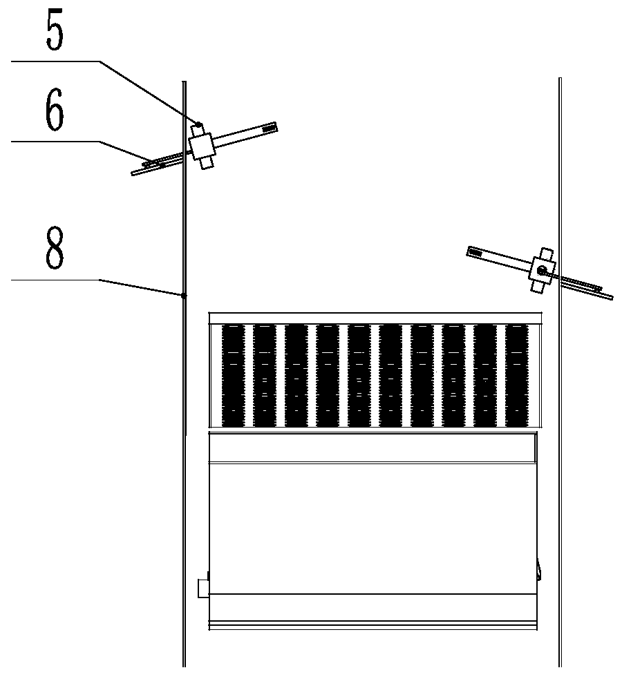
[0049] A wind speed monitoring device 6 is installed at the feed end and the waste outlet of the cleaning space, and the torque sensor 4 is installed on the grain auger shaft. The control method of embodiment 1 of the present invention, such as Figure 10 As shown, specifically:

[0050] Due to the different planting conditions and growth conditions of the fields where the combine harvester operates, it is impossible to set a unified standard to judge whether the airflow measured by the wind speed sensor 602 is within the normal range. The plots in a certain area are tested for cutting, and the torque value under normal working conditions and the airflow state measured by the wind speed sensors on both sides of the wall are respectively obtained, and the data are stored in the computer to obtain the torque standard library (X 1 ~X 2 ), through the sieve airflow standard library 1 (X 左min ~X 左max ) and sieve airflow standard library 2(X 右min ~X 右max ).

[0051] When work...

Embodiment 2

[0053] A wind speed monitoring device 6 is respectively installed at the feeding end and the miscellaneous outlet of the cleaning space, and the acceleration sensor 4' is adsorbed on the outside of the slide plate below the grain auger. The control method of embodiment 2 of the present invention, such as Figure 12 As shown, specifically:

[0054] Due to the different planting conditions and growth conditions of the fields where the combine harvester operates, it is impossible to set a unified standard to judge whether the airflow measured by the wind speed sensor 602 is within the normal range. Therefore, before the combine harvester starts formally, first Trial cutting is carried out on a certain area of ​​land, and the impact vibration of the grains on the sliding plate under normal working conditions and the airflow state measured by the wind speed sensors on the two side walls are respectively obtained, and the data are stored in the computer to obtain the shock vibration...


PUM


Abstract

The invention provides a sorting screen surface material status monitoring system and a control method thereof and a combine harvester. Sorting space is internally provided with a sorting screen, and the bottom of the sorting screen is provided with a kernel conveying device. The sorting screen surface material status monitoring system also comprises wind speed monitoring devices and a control system, and the sorting space located above the sorting screen is internally provided with at least one wind speed monitoring device used for monitoring the change of air flow through the screen; at least one sensor is used for detecting status parameters of the kernel conveying device, and the control system judges whether or not the sorting screen is blocked according to the change of the air flow through the screen and the status parameters of the kernel conveying device. The sorting screen surface material status monitoring system can judge whether or not kernels pass through the screen difficultly by monitoring the change of the air flow through the screen in the space above the sorting screen and the change of the auger torque of the kernels.

Description

technical field [0001] The invention relates to the field of agricultural machinery, in particular to a material state monitoring system and control method on a cleaning screen surface and a combine harvester. Background technique [0002] The cleaning device is one of the core components of the combine harvester. During the operation of the combine harvester, due to insufficient threshing or feeding fluctuations, the grain prolapses tend to accumulate on the sieve surface, making it difficult for the grain to pass through the sieve. , the airflow blown out by the fan is difficult to pass through the screen, which will cause the problem of blockage of the screen surface and increase the loss. Under the action of centrifugal force, the lateral distribution of the prolapse of the axial flow threshing and separation device shows a law of high on both sides and low in the middle, which will lead to cleaning and screening. Problems such as accumulation of protruding substances on...

Claims


Application Information

Patent Timeline
Patent Type & Authority Applications(China)
IPC IPC(8): A01D41/127
CPCA01D41/127
Inventor 马征韩敏李耀明高洪燕王振宇路恩马克超
Owner JIANGSU UNIV
Why Eureka
Try Eureka