
Electroosmosis waterproof device and electroosmosis waterproof system

A technology of electroosmosis and equipment, applied in the direction of electrodialysis, semipermeable membrane separation, chemical instruments and methods, etc., can solve the problems of equipment burning, current increase, and failure to achieve waterproof effect, etc., and achieve good waterproof effect

Active Publication Date: 2019-09-20
派纳克斯有限公司
View PDF11 Cites 1 Cited by
  • Summary
  • Abstract
  • Description
  • Claims
  • Application Information

AI Technical Summary

Problems solved by technology

[0006] In view of this, the purpose of the present invention is to overcome the deficiencies of the prior art, and provide an electro-osmotic waterproof device, which solves the problem that in the conventional waterproof application of the prior art, the current in the system increases at the same time, so that the current of the positive pole and the negative pole cannot be carried out. The adjustment equipment is easy to be overloaded and burned, so that the waterproof effect cannot be achieved

Method used


Image

  • Electroosmosis waterproof device and electroosmosis waterproof system
  • Electroosmosis waterproof device and electroosmosis waterproof system
  • Electroosmosis waterproof device and electroosmosis waterproof system

Examples


Embodiment 1

[0058] figure 1 It is a structural schematic diagram of the electro-osmotic waterproof device provided by Embodiment 1 of the present invention.

[0059] Such as figure 1 As shown, this embodiment includes: a power converter 101, a first acquisition component 102, a processor 103 and a signal output component 104; the first acquisition component 102 is connected to the power converter 101 and the processor 103 respectively, and the processor 103 It is connected with the signal output assembly 104, and the signal output assembly 104 is connected with at least two positive and negative electrode assemblies of the target infiltration object.

[0060] Positive and negative components include positive coils and negative rods. The positive coils are arranged in the working surface that needs to be waterproofed. The working surface can be an indoor wall or an underground wine cellar, underground audio-visual room, underground valuable storage space, underground survival space, etc. ...

Embodiment 2

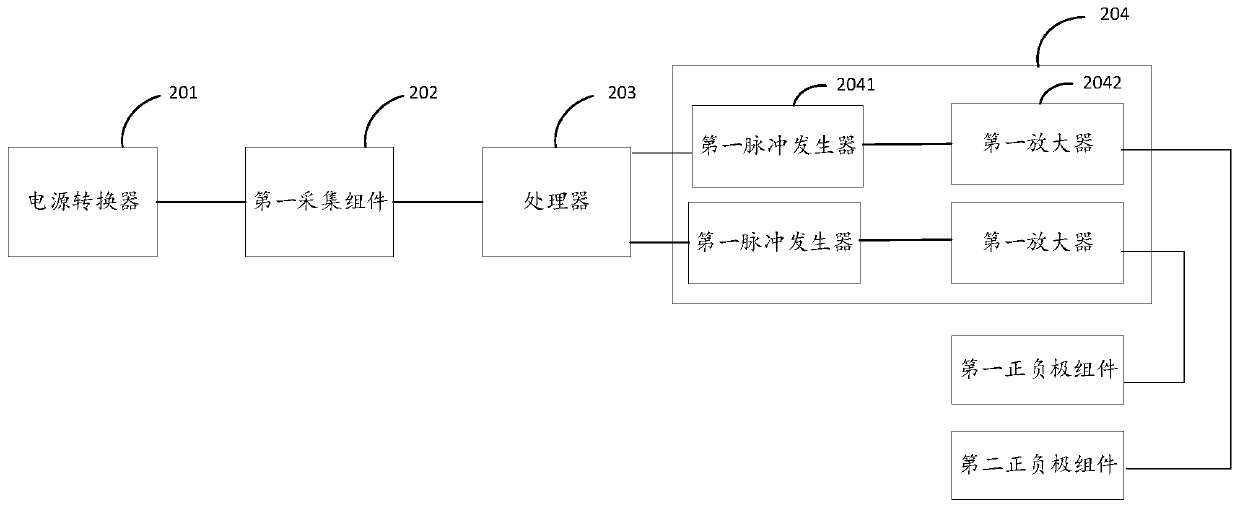
[0074] figure 2 It is a schematic structural diagram of the electro-osmotic waterproof device provided by the second embodiment of the present invention.

[0075] Such as figure 2 As shown, this embodiment is based on the first embodiment above, further, the signal output component 204 includes: at least two first pulse generators 2041 and a first amplifier corresponding to each first pulse generator 241 2042; figure 2 The figure in the figure is a structural schematic diagram of an electro-osmotic waterproof device with two first pulse generators, and the corresponding number of first amplifiers is also two. When the number of the first pulse generator is more than two, its working principle is the same as the number of two first pulse generators.

[0076] The first collection component 202 is connected with the power converter 201 and the processor 203 respectively, and the processor 203 is connected with the signal output component 204, wherein each first pulse genera...

Embodiment 3

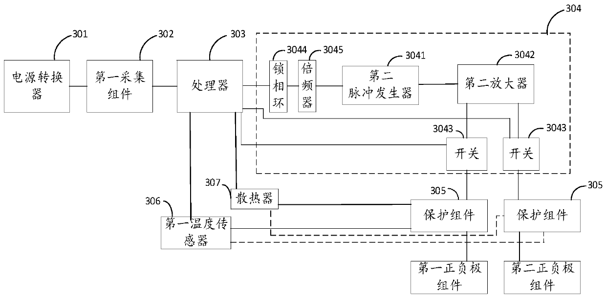
[0083] image 3 It is a schematic structural diagram of the electro-osmotic waterproof device provided by Embodiment 3 of the present invention.

[0084] Such as image 3 As shown, in this embodiment, on the basis of the first embodiment above, further, the signal output component includes: a second pulse generator 3041, a second amplifier 3042 and at least two switches; the control instruction includes: a signal trigger instruction and a target switch control command;

[0085]The second pulse generator 3041 is connected to the processor 303 and the second amplifier 3042 respectively, the second amplifier 3042 is connected to the positive and negative components corresponding to the switch 3043 through each switch 3043, and each switch 3043 is connected to the processor 303 connected;

[0086] The switch 3043 can be an analog electronic switch or an electromagnetic switch, connected between the second amplifier 3042 and each positive and negative component, and connected wi...


PUM


Abstract

The invention discloses an electroosmosis waterproof device. The electroosmosis waterproof device comprises a first acquisition component. The first acquisition component is connected with a power adapter and a processor, the processor is connected with a signal output component, and the signal output component is connected with at least two positive and negative components of a target osmosis object. The power adapter coverts alternating-current voltages provided by a power supply into direct-current working voltages for the electroosmosis waterproof device. The first acquisition component acquires first power supply information values output by the power adapter and sends the values to the processor. The processor sends control commands of the target positive and negative components to the signal output component, wherein the control commands are generated when the first power supply information values are greater than a preset reference information value. The signal output component receives the control commands of the target positive and negative components and outputs impulse electric signals to the target positive and negative components. The number of the discharging positive and negative components is dynamically adjusted, the problem that all the positive and negative components discharge electricity to be burned out when currents are overlarge is avoided, and a good waterproofing effect is achieved.

Description

technical field [0001] The invention relates to the technical field of electroosmotic waterproofing, in particular to an electroosmotic waterproofing device and system. Background technique [0002] Existing residences and underground spaces are mostly built with concrete and masonry. In concrete and masonry structures, water can infiltrate into the structure in many ways, and the simplest form is to use the gravity of water itself to pass through pores or various A kind of crack enters the interior of the structure, and water seepage can also penetrate into the interior of the structure through the organization of capillaries in the structure. Dry concrete can absorb the water in the room and reduce the humidity of the indoor air. At the same time, it can avoid the growth of mold caused by humidity, and the spores of mold can float and multiply in the indoor air, avoiding the occurrence of various diseases caused by mold. [0003] However, after the concrete absorbs water,...

Claims


Application Information

Patent Timeline
Patent Type & Authority Applications(China)
IPC IPC(8): B01D61/42E04B1/66
CPCB01D61/427E04B1/66
Inventor 钟山
Owner 派纳克斯有限公司
Learn More