W-shaped bottoming cycle airflow pneumatic flotation machine

An inflatable, bottom-circulating technology, used in flotation, solid separation, etc., can solve the problems of inability to guarantee air, scrape out, affect the efficiency of refining foam, etc., and achieve the effect of improving refining efficiency and improving sorting efficiency.

Inactive Publication Date: 2019-09-20
ANHUI ZHONG NENG MACHINERY MFG
View PDF0 Cites 4 Cited by
  • Summary
  • Abstract
  • Description
  • Claims
  • Application Information

AI Technical Summary

Problems solved by technology

[0004] The purpose of the present invention is to provide a W-type bottom circulating airflow inflatable flotation machine to solve the traditional inflatable flotation machine. When in use, the inflatable mechanism communicates with the slurry tank through the air guide tube, and the air flow enters the slurry tank in one direction with the air guide tube. The traditional inflatable flotation machine cannot ensure enough air when the external air is pressed in one direction, that is, it cannot ensure that the ore particles and the air bubbles can fully contact, which affects the efficiency of the refined foam; when the refined foam floats After the mineralized foam is formed on the surface of the pulp, the traditional inflatable flotation machine uses a scraper to scrape out the useful foam. The scraper is mostly a plate directly installed on the rotating shaft, and its scraping efficiency is low. When mineralized foam More often, the technical problem that the foam cannot be scraped out in time

Method used


Image

  • W-shaped bottoming cycle airflow pneumatic flotation machine
  • W-shaped bottoming cycle airflow pneumatic flotation machine
  • W-shaped bottoming cycle airflow pneumatic flotation machine

Examples


Embodiment Construction

[0035] The technical solutions of the present invention will be clearly and completely described below in conjunction with the embodiments. Apparently, the described embodiments are only some of the embodiments of the present invention, not all of them. Based on the embodiments of the present invention, all other embodiments obtained by persons of ordinary skill in the art without creative efforts fall within the protection scope of the present invention.

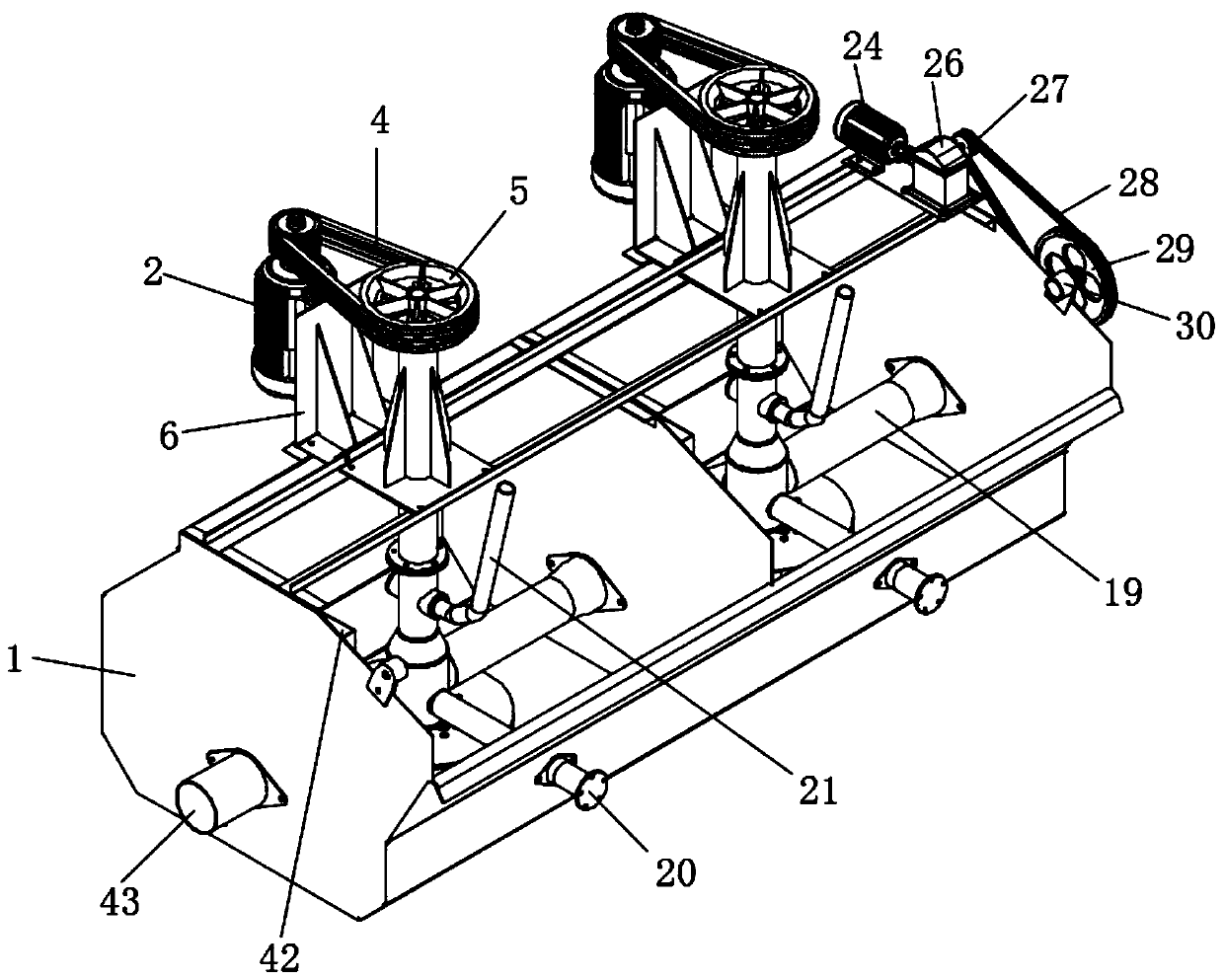
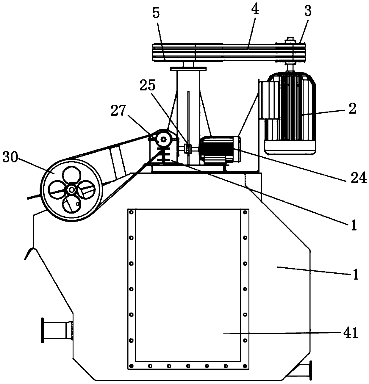
[0036] see Figure 1-7 , a W-type bottom circulation airflow inflatable flotation machine, including: a slurry tank 1, a stirring mechanism located at the upper end of the slurry tank 1 for stirring the pulp in the slurry tank 1, and a stirring mechanism located at the upper end of the slurry tank 1 for Scraper 39 for scraping out mineralized foam.

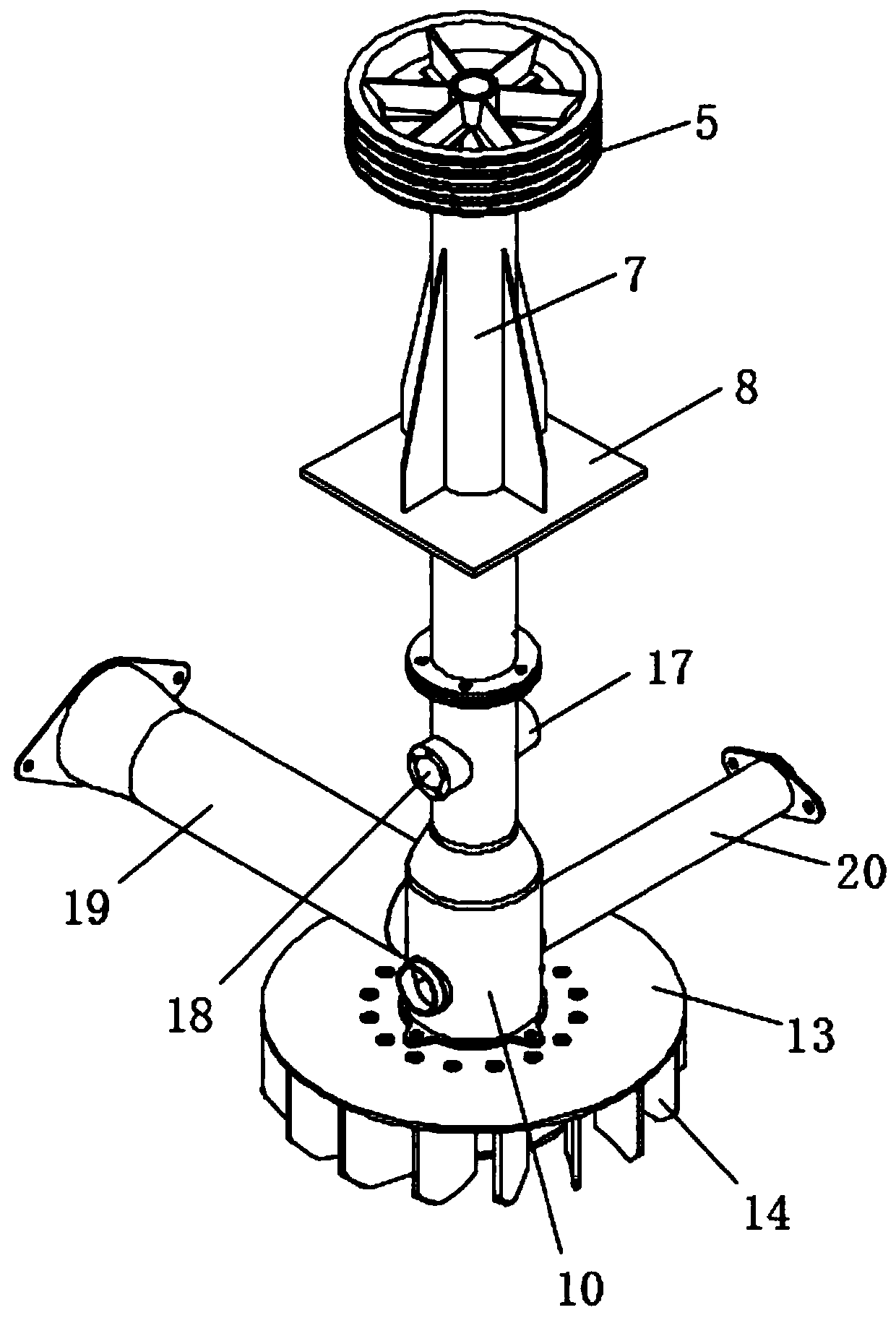
[0037] The stirring mechanism comprises a main shaft 12, a mounting plate 13, a guide plate 14 and a rotating blade 15, wherein the top of the main shaft 12 extends upwards th...


PUM


Abstract

The invention discloses a W-shaped bottoming cycle airflow pneumatic flotation machine. The W-shaped bottoming cycle airflow pneumatic flotation machine comprises an ore pulp receiving groove, a stirring mechanism which is located at the upper end of the ore pulp receiving groove and used for stirring ore pulp in the ore pulp receiving groove, and scraper boards which are located at the upper end of the ore pulp receiving groove and used for scraping off mineralized bubbles, by fixedly installing an air inlet pipe at one end of a first installation hole, the air inlet pipe communicates with a second protective shell, moreover, the top end of the air inlet pipe communicates with an air blower, and a circulating air pipe communicates with the second protective shell, so that when air is pressed into the air inlet pipe by the air blower, the air enters the ore pulp receiving groove when under pressure; and when the air and the ore pulp cannot be completely mixed, the air which is pressed in is pressed into the ore pulp receiving groove from the circulating air pipe by the air blower again when under pressure, and thus cycle airflow is generated, so that the defect that when a traditional pneumatic flotation machine presses external air in a single direction, enough air cannot be guaranteed, and full contact among mineral grains and bubbles cannot be guaranteed, so that bubble refining is affected is solved, and the refining efficiency is improved.

Description

technical field [0001] The invention relates to the structural field of an inflatable flotation machine, specifically a W-shaped bottom circulating airflow inflatable flotation machine, belonging to the application technical field of a circulating airflow inflatable flotation machine. Background technique [0002] The flotation machine is suitable for the separation of non-ferrous and ferrous metals. Generally, the flotation machine is driven by the V-belt drive of the motor to rotate the impeller, which generates centrifugal action to form a negative pressure. At the same time, the foam is refined so that the minerals adhere to the foam and float to the surface of the slurry to form a mineralized foam. [0003] In the traditional inflatable flotation machine, the inflatable mechanism communicates with the slurry tank through the air guide tube when in use, and the air flow enters the slurry tank in one direction along with the air guide tube to mix with the pulp. The tradit...

Claims


Application Information

Patent Timeline
Patent Type & Authority Applications(China)
IPC IPC(8): B03D1/22B03D1/14
CPCB03D1/1462B03D1/22
Inventor 杜友花
Owner ANHUI ZHONG NENG MACHINERY MFG
Why Eureka
Try Eureka