Full numerical control robot bending unit
A technology for robots and robot bases, applied in safety equipment, feeding devices, positioning devices, etc., can solve problems such as affecting processing accuracy and processing quantity, potential safety hazards, low manual bending efficiency, etc., to save manpower and material resources, improve The effect of production efficiency
- Summary
- Abstract
- Description
- Claims
- Application Information
AI Technical Summary
Problems solved by technology
Method used
Image

Examples
Embodiment 1
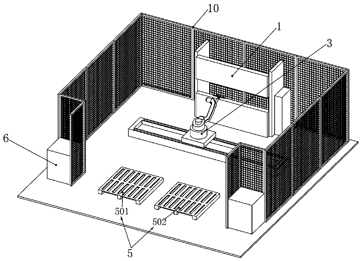
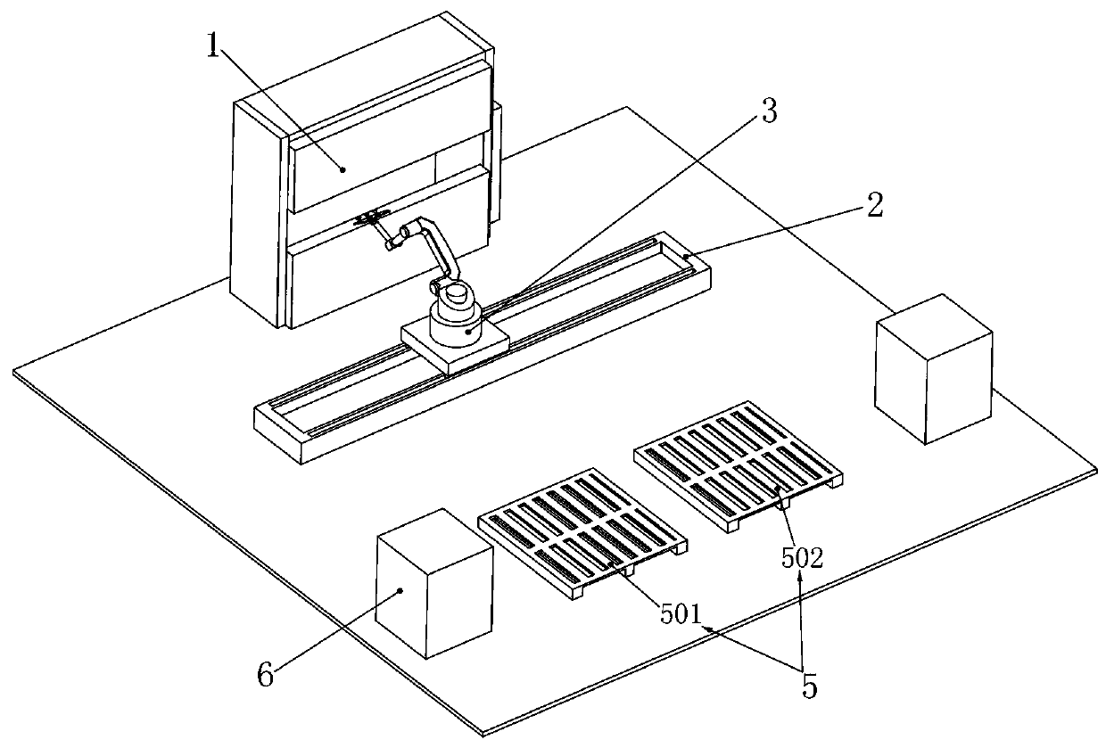
[0025] Embodiment 1, the present invention is a fully numerical control robot bending unit, which is characterized in that it includes a bending machine 1, the selection of the bending machine 1 can be determined according to actual production needs, and the bending machine 1 is fixed on the ground of the production area. A horizontally fixed robot slide rail 2 is installed on the front of the bending machine 1. The robot slide rail 2 is a cuboid and fixed on the ground by bolts. A robot 3 is slidably installed on the robot slide rail 2. Move left and right on the slide rail 2, the distance between the robot slide rail 2 and the bending machine 1 is smaller than the maximum working range of the robot 3, so that when the robot 3 slides on the robot slide rail 2, it can cooperate with the bending machine 1 Bending, the robot 3 is rotated and installed with a gripper 4, the gripper 4 can rotate on the robot 3, when the gripper 4 grasps the sheet material for bending, after the she...
Embodiment 2
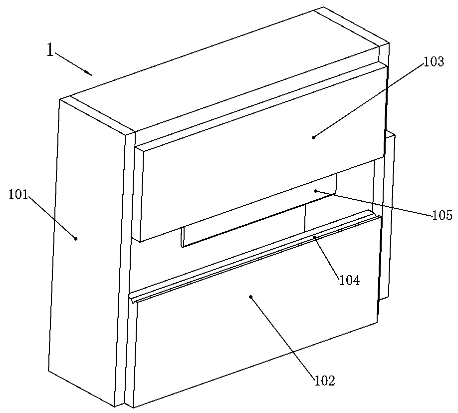
[0026] Embodiment 2. On the basis of Embodiment 1, the bending machine 1 includes a square outer frame 101. The square outer frame 101 is fixed on the ground and can be fixed by bolts or other common fixing methods. The square The lower end of the front end of the outer frame 101 is fixedly equipped with a force plate 102, which can be welded on the square outer frame 101, and the sheet material grabbed by the robot 3 will be sent to the force plate 102 at first, and the square outer frame The upper end of the front face of 101 is slidably installed with a knife rest 103 up and down, the knife rest 103 can slide up and down on the square outer frame 101, the knife rest 103 is connected with a hydraulic cylinder, this hydraulic cylinder is connected with the console 6, and the top of the force plate 102 There is a V-shaped groove 104 on the surface, and the V-shaped groove 104 can make the sheet material be pressed out at different angles. The bottom surface of the knife rest 10...
Embodiment 3
[0027] Embodiment 3, on the basis of Embodiment 1, the robot 3 includes a robot base 301, the robot base 301 is slidably installed on the robot slide rail 2, and the first arm 302 is rotatably installed on the robot base 301, and the first arm 302 Can rotate clockwise or counterclockwise on the robot base 301, the first arm 302 is connected with a first drive motor, the rotation of the first drive motor can realize the rotation of the first arm 302, and the rotation of the first arm 302 is equipped with a second arm 303 , the second arm 303 is bow-shaped, its lower end is rotatably mounted on the first arm 302, the second arm 303 can swing up and down on the first arm 302, the second arm 303 is connected with a second driving motor, and the second driving motor can rotate Realize the swing of the second arm 303, the upper end of the second arm 303 is rotated and installed with the third arm 304, the third arm 304 can swing up and down on the second arm 303, the third arm 304 is...
PUM
 Abstract
Description
Claims
Application Information