
Top cutter identification and elimination method for five-axis plunge milling of integral impeller

A technology of integral impeller and plunge milling, applied in metal processing equipment, metal processing mechanical parts, milling machine equipment, etc., can solve the problems affecting semi-finishing efficiency, excessive cutting allowance, etc., to improve roughing efficiency and improve efficiency. Effect

Active Publication Date: 2021-01-15
DALIAN UNIV OF TECH
View PDF6 Cites 0 Cited by
  • Summary
  • Abstract
  • Description
  • Claims
  • Application Information

AI Technical Summary

Problems solved by technology

Gradually reducing the depth of plunging and milling will lead to a reduction in the depth of plunging and milling for subsequent processing, which will leave more cutting allowance for subsequent processing and affect the efficiency of semi-finishing
For three-axis machining, the remaining material due to the gradual reduction of the plunge-milling depth can be quickly removed by face milling, but for the five-axis machining of the overall impeller, if the method of gradually reducing the plunge-milling depth is used to eliminate the top knife, the residual workpiece on the hub surface Material can only be removed by spot milling, seriously affecting the efficiency of semi-finishing

Method used


Image

  • Top cutter identification and elimination method for five-axis plunge milling of integral impeller
  • Top cutter identification and elimination method for five-axis plunge milling of integral impeller
  • Top cutter identification and elimination method for five-axis plunge milling of integral impeller

Examples


Embodiment 1

[0041] Such as Figure 1 to Figure 7 As shown, the present invention provides a top knife identification and removal method for five-axis plunge milling of an integral impeller, which specifically includes the following steps:

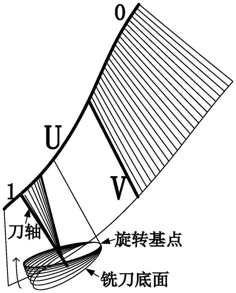
[0042] Step 1: In the process of five-axis plunge milling, the bottom end of the tool for two adjacent plunge milling is recorded as O i-1 , O i , where the previous plunge milling is recorded as tool axis i-1, and the latter plunge milling is tool axis i, such as figure 1 shown. When plunging and milling the top cutter occurs, the bottom circle of the milling cutter of the cutter axis i is O i Not completely at the bottom circle O of the tool axis i-1 i-1 above, touching the unprocessed area of ​​the tool axis i-1, which means the bottom circle O of the i-th tool in plunge milling 1 and the bottom circle O of the i-1th knife i intersect.

[0043] Therefore, the identification model of the top cutter for five-axis plunge milling is defined as: t...


PUM


Abstract

The invention provides a cutter propping recognizing and removing method for five-axis inserting milling processing of a complete impeller. The method comprises the following steps: S1, recognizing of cutter propping, namely, determining whether circles at the bottom parts of cutters which are subjected to two successive inserting and milling are intersected; and if so, determining that cutter propping occurs; S2, selecting of a base rotating point, namely, selecting an inserting point, far away from an intersecting line, from two intersecting points between the circle at the bottom part of the cutter which is inserted and used for milling in the i time and an extending surface of a straight texture surface formed by axes of the cutters in a whole row; S3, removing of cutter propping, namely, rotating to obtain a new cutter axis and a new cutter position point; and S4, detecting of cutter propping, namely, returning to step S1; calculating to determine whether cutter propping occurs; and if so, repeating steps S2 and S3 until the cutter propping circumstance is removed. According to the method, the problem of cutter propping in inserting and milling is removed by adjusting the cutter axis vector and the cutter position point, and thus abnormal processing such as overload and vibration caused by cutter propping in inserting and milling can be avoided; and subsequent processing efficiency is not influenced while high inserting milling processing efficiency is ensured.

Description

technical field [0001] The invention relates to the field of plunging and milling processing of integral impellers, in particular to a method for identifying and eliminating top knives in trajectory planning of five-axis plunging and milling. Background technique [0002] The plunge milling method, also known as the Z-axis milling method, has a cutting efficiency 4 to 5 times higher than that of traditional milling, especially in the high removal rate of difficult-to-cut materials. The plunge milling process is fed along the tool axis, has the characteristics of small radial cutting force, good cutting stability, and allows the use of tools with a large length-to-diameter ratio. It is very suitable for rough machining of deep cavity and deep groove parts. Plunge milling is currently a cutting method with high material removal efficiency, which can significantly reduce processing time. At present, the three-axis plunge-milling module has become the standard configuration of ...

Claims


Application Information

Patent Timeline
Patent Type & Authority Patents(China)
IPC IPC(8): B23C9/00B23Q17/00
CPCB23C9/00B23Q17/00
Inventor 魏兆成王敏杰李国彦
Owner DALIAN UNIV OF TECH
Learn More